EasyManuals Logo

Epson RC700 User Manual

Epson RC700
316 pages
To Next Page IconTo Next Page
To Previous Page IconTo Previous Page
Page #76 background imageLoading...
Page #76 background image
Setup & Operation 11. I/O Connector
64 RC700 / RC700-A Rev.23
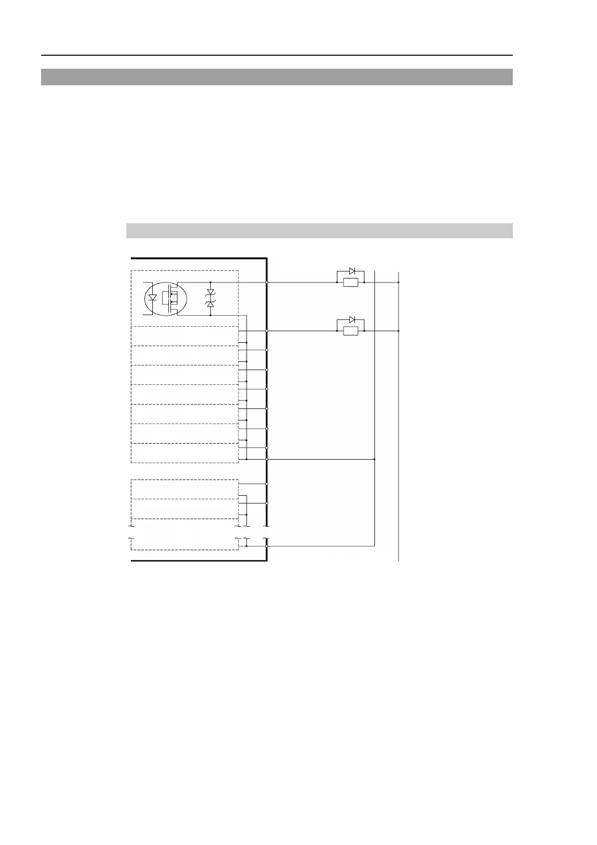
11.2 Output Circuit
Rated Output Voltage : +12 V to 24 V ±10%
Maximum Output Current : TYP 100 mA/1 output
Output Driver : PhotoMOS Relay
On-State Resistance (average) : 23.5 Ω or less
Two types of wiring are available for use with the nonpolar PhotoMOS relay in the output
circuit.
Typical Output Circuit Application 1
10 Output No.0
I/O-1
(Same)
Omit
+DC
29 Output No.8
30 Output No.9
11 Output No.1
12 Output No.2
13 Output No.3
14 Output No.4
15 Output No.5
27 Output No.6
28 Output No.7
17 Output No.0 to 7 common (GND)
Load
L
GND
L
33 Output No.8 to 15 common (GND)
(Same)
(Same)
(Same)
(Same)
(Same)
(Same)
(Same)
(Same)

Table of Contents

Questions and Answers:

Question and Answer IconNeed help?

Do you have a question about the Epson RC700 and is the answer not in the manual?

Epson RC700 Specifications

General IconGeneral
Maximum Axes16
Communication InterfacesEthernet, EtherNet/IP, PROFINET, PROFIBUS, CC-Link, RS-232C, USB
Safety StandardsISO 10218-1, ISO/TS 15066, IEC 61508, IEC 61511, ANSI/RIA R15.06
Operating SystemVxWorks
Power Supply24 VDC

Related product manuals