EPSON Stylus C67/C68/D68 Revision A
OPERATING PRINCIPLES Electrical Circuit Operating Principles 26
2.2.4 Ink System Mechanism
The Ink system mechanism consists of pump mechanism and capping mechanism with
wiper mechanism.
2.2.4.1 Pump Unit Mechanism
With this printer, when the PF motor turns, power is always transmitted to the ink
system.
Note *: The PF Motor rotational direction = seen from the left side of the printer.
2.2.4.2 Capping Mechanism
The Capping mechanism covers the printhead with the cap to prevent the nozzle from
increasing viscosity when the printer is in stand-by state or when the printer is off.
2.3 Electrical Circuit Operating Principles
The electric circuit of the Stylus C67/C68/D68 consists of the following boards.
Main board: C616 MAIN Board
Power supply board: C616 PSB/PSB board
Panel board: C616 PNL board
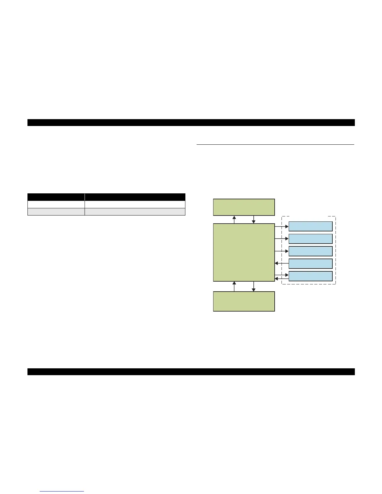
This section provides block diagram of both C616 MAIN Board and C616 PSB/PSE
Board, C616 PNL board.
Figure 2-3. Electrical Circuit Block Diagram
Table 2-3. PF Motor Rotational Direction & Ink System Mechanism
Directions* Functions
Counterclockwise
• Absorbs the ink by the Pump Unit
Clockwise
• Release pump.
Printer Mechanism
CR Motor
PF Motor
Head Driver Board
Sensors
CSIC Unit
C616PSB/C616PSE Board
+42V
PowerOFF
C616 Main Board
C616 PNL Board

 Loading...


