EPSON Stylus C67/C68/D68 Revision A
DISASSEMBLY/ASSEMBLY Disassembly Procedures 41
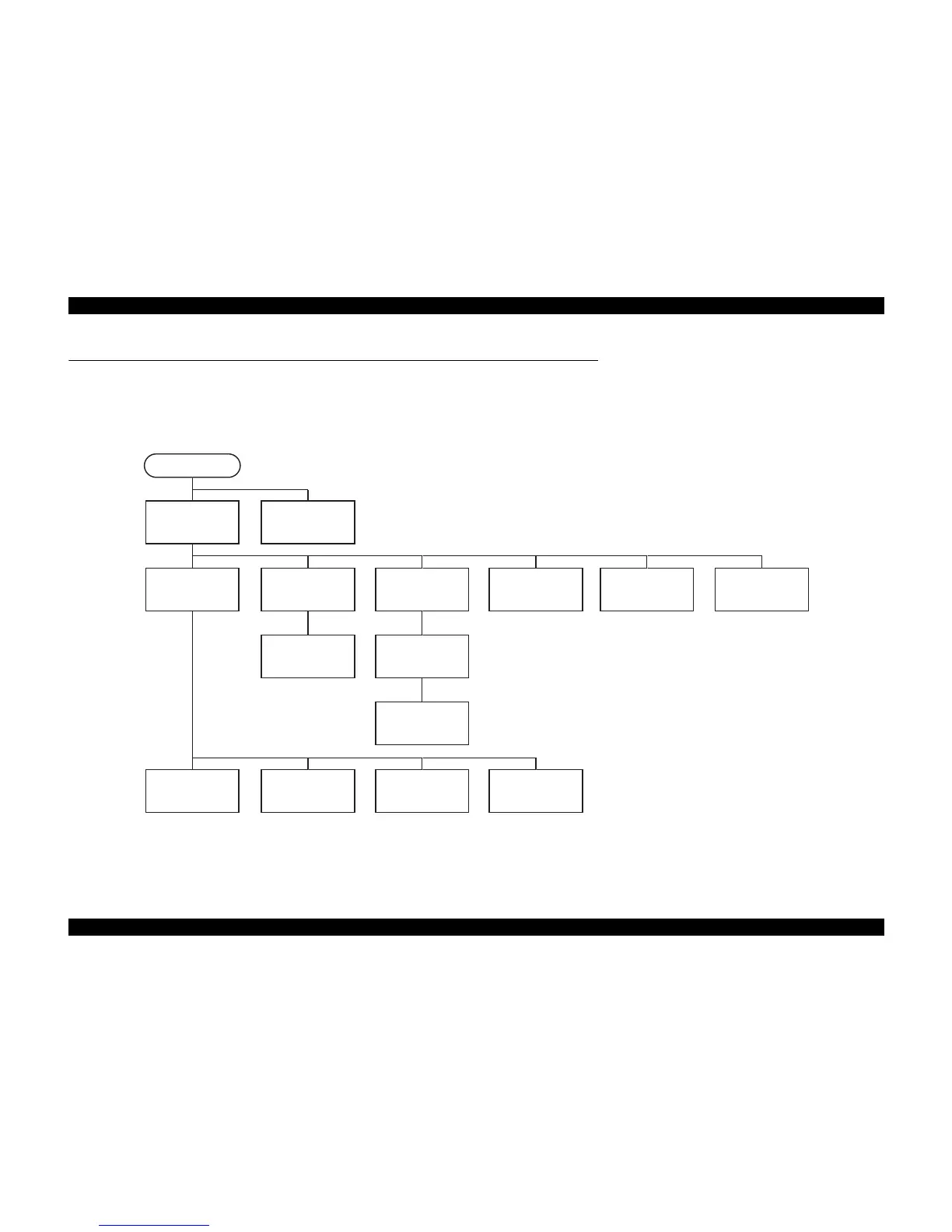
4.3 Disassembly Procedures
This section explains the procedures for disassembling the product.
Unless otherwise stated, reassembly should be carried out in the reverse order of the disassembly procedure.
For detailed engagement relations among main components, refer to the exploded diagrams in the Appendix.
When disassembling each unit, refer to the pages described in the chart below.
Figure 4-1. Disassembling Flowchart (1)
"Housing, Upper"
4.3.1.1 (p. 43)
START
"Stacker Assy."
4.3.1.2 (p. 44)
"ASF Unit"
4.3.1.3 (p. 44)
"Hopper/Retard Roller
Unit"
4.3.1.4 (p. 45)
"Main Board"
4.3.2.1 (p. 52)
"Panel Board"
4.3.2.2 (p. 54)
"PS Board"
4.3.2.3 (p. 55)
"CR Timing Belt"
4.3.3.5 (p. 60)
"CR Motor"
4.3.3.6 (p. 61)
"Front Frame"
4.3.3.7 (p. 62)
"CR Encoder Scale"
4.3.3.8 (p. 63)
"CR Cable Head
Cover"
4.3.3.9 (p. 64)
"Paper Guide, Upper
Assy."
4.3.3.14 (p. 70)
"Eject Roller"
4.3.3.15 (p. 70)
"Paper Guide, Front
Assy."
4.3.3.16 (p. 72)
 Loading...


