EPSON Stylus C67/C68/D68 Revision A
DISASSEMBLY/ASSEMBLY Disassembly Procedures 42
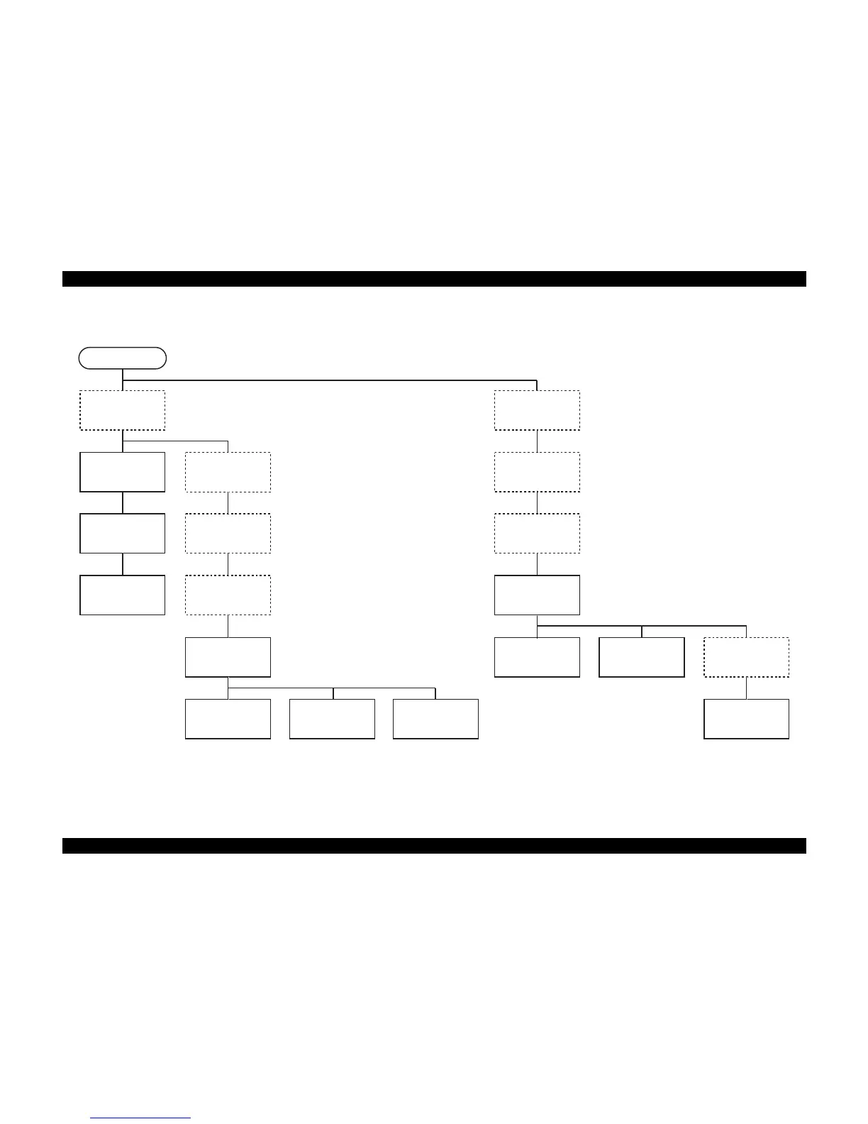
Figure 4-2. Disassembling Procedure (2)
START
"Panel Board"
4.3.2.2 (p. 54)
"Holder Shaft Unit"
4.3.3.2
(p. 56)
4.3.3.2 (p. 56)
"Spool Gear 36.8/Extension
Spring 0.143/Clutch"
4.3.3.3 (p. 58)
"PE Sensor Board/PE
Detection Lever/Idle
Roller"
4.3.3.4 (p. 59)
"Front Frame"
4.3.3.7 (p. 62)
"CR Encoder Scale"
4.3.3.8 (p. 63)
"CR Cable Head
Cover"
4.3.3.9 (p. 64)
"CR Unit"
4.3.3.10 (p. 64)
"Printhead Assy."
4.3.3.11 (p. 67)
"CR Encoder Sensor
Board"
4.3.3.12 (p. 68)
"CSIC Board"
4.3.3.12 (p. 68)
"PS Board"
4.3.2.3 (p. 55)
"Stacker Assy."
4.3.1.2 (p. 44)
"Paper Guide, Front
Assy."
4.3.3.16 (p. 72)
"Housing, Lower Assy."
4.3.1.5 (p. 47)
"Waste Ink Pad"
4.3.1.6 (p. 51)
"PF Motor"
4.3.3.18 (p. 75)
"Holder Shaft Unit"
4.3.3.2 (p. 56)
"Pump Unit/Cap Unit"
4.3.3.17 (p. 73)
* Procedure in the broken-line is NOT the
shortest removing procedure, but the
passing point for the next removing
procedure.

 Loading...


