EPSON Stylus Color 440/640/740 Revision A
Chapter 1 Product Description 28
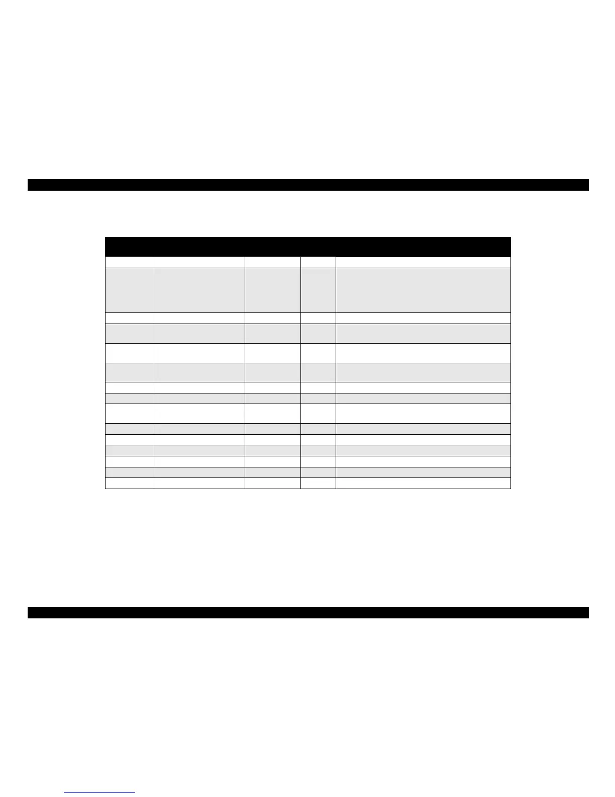
Table 1-12. Parallel I/F Reverse Channel
Pin No. Signal Name
Return GND
Pin
In/Out Functional Description
1 HostClk 19 I Host clock signal.
2-9 Data0-7 20-27 I
The DATA0 through DATA7 signals represent data
bits 0 to7, respectively. Each signal is at high level
when data is logical 1 and low level when data is
logical 0. These signals are used to transfer the 1284
extensibility request values to the printer.
10 PrtClk 28 O Printer clock signal.
11 PtrBusy, Data Bit-3,7 29 O
Printer busy signal and reverse channel transfer data
bit 3 or 7.
12 AckData Req, DataBit-2,6 28 O
Acknowledge data request signal and reverse channel
transfer data bit 2 or 6.
13 Xflag, DataBit-1,5 28 O
X-flag signal and reverse channel transfer data bit 1 or
5.
14 HostBusy 30 I Host busy signal.
31 /INIT 30 I Not used.
32 /DataAvail, DataBit-0,4 29 O
Data available signal and reverse channel transfer
data bit 0 or 4.
36 1284-Active 30 I 1284 Active Signal
18 Logic-H ---- O Pulled up to +5V via 3.9K ohm resister.
35 +5V ---- O Pulled up to +5V via 3.3K ohm resister.
17 Chassis GND ---- --- Chassis GND.
16,33, 9-30 GND ---- --- Signal GND.
15,34 NC ---- --- Not connected.
Note) In/Out refers to the direction of signal flow from the printer’s point of view.
 Loading...