EPSON Stylus CX4900/CX4905/CX5000/DX5000/DX5050/CX5900/CX6000/DX6000/DX6050 Revision A
DISASSEMBLY/ASSEMBLY Printer Section 131
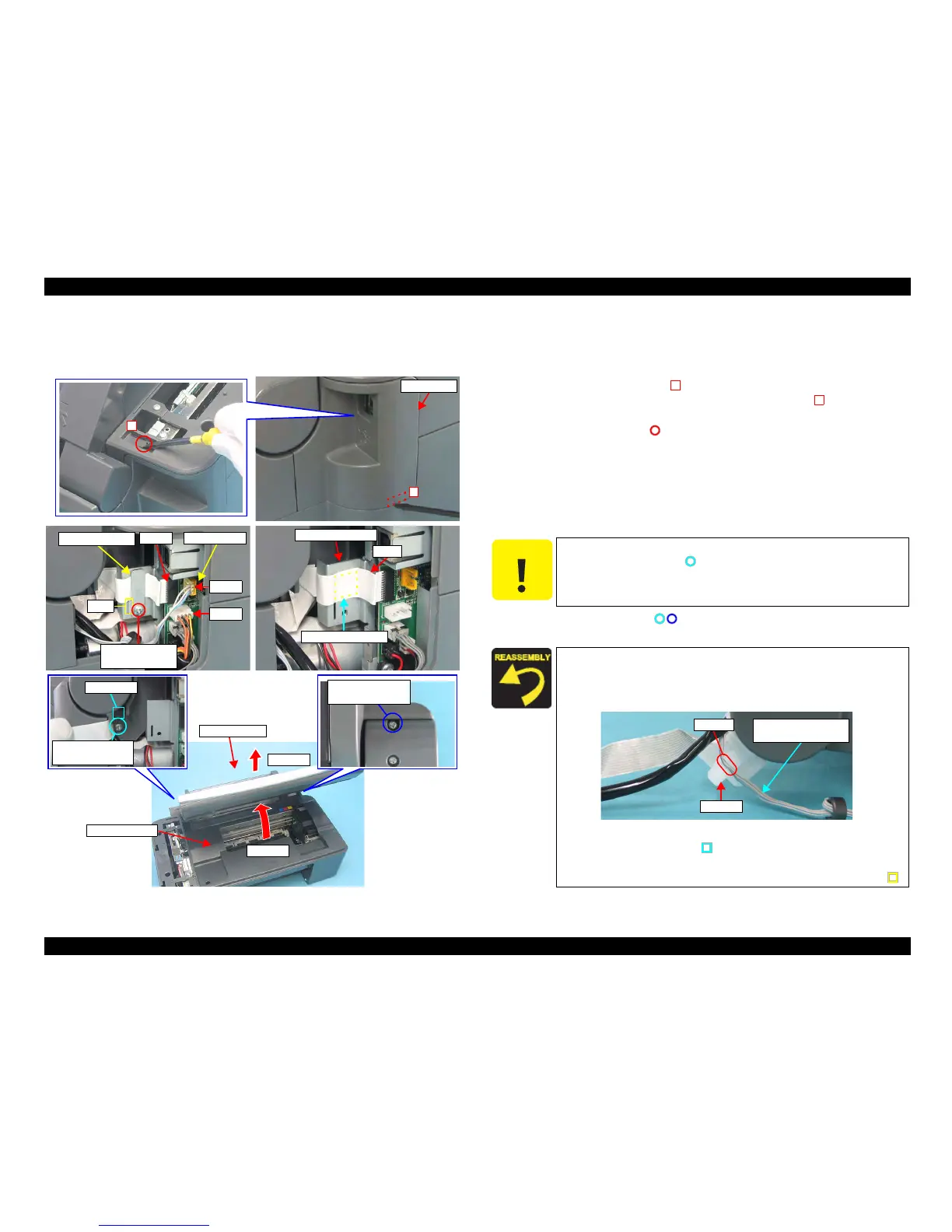
4.4.5 Scanner Unit
External view (1)
Figure 4-7. Removing Scanner Unit
Part/Unit
that should be removed before removing Scanner Unit
Document Cover / Panel Unit
Removal procedure
1. Lift and release the tab (x1, ) that secure the USB Cover with a precision
screwdriver (-) from the top side, then release the tab (x1, ) and remove the
USB Cover.
2. Remove the screw (x1, ) that secure the FFC Shield Plate, and remove the
FFC Shield Plate.
3. Disconnect the following Connector Cables and FFC from the connectors on
the Main Board.
• CN10: Scanner Motor Connector Cable
• CN11: Scanner Carriage FFC
• CN13: Scanner HP Sensor Connector Cable
4. Remove the
screws (x2, ) that secure the Scanner Unit.
5. Open the Scanner Unit, and remove it by pulling out upward.
USB Cover
2
1
CN10
CN13
CN11
Main Board
FFC Shield Plate
C.B.S. 3x6 F/Zn
(6±1kgfcm)
Rib
FFC
Main Board Unit
Double-sided Tape
Step 5-1
Step 5-2
C.B.P. 3x10 F/Zn
(6±1kgfcm)
Guide Pin
C.B.P. 3x10 F/Zn
(6±1kgfcm)
Scanner Unit
Housing, Upper
C A U T I O N
Do not damage the Scanner Carriage FFC when removing/
installing the screw ( ).
The Scanner Carriage FFC is fastened with the double-sided
tape, so be careful not to damage the FFC when removing it.
Do not pinch the FFC or any Connector Cables between the
Scanner Unit and the Housing, Upper.
Route the Scanner HP Sensor Connector Cable around the
groove of Hinge L.
Figure 4-8. Routing Co
nnector Cable
Al
ign the guide pin (x1, ) of the Scanner Unit and the
positioning hole (x1) of the Housing Upper.
Insert
the rib (x1) of the FFC Shield Plate into the notch (x1, ).
1
2
Scanner HP Sensor
Connector Cable
Hinge L
Groove
 Loading...


