EPSON Stylus CX4900/CX4905/CX5000/DX5000/DX5050/CX5900/CX6000/DX6000/DX6050 Revision A
DISASSEMBLY/ASSEMBLY Printer Section 143
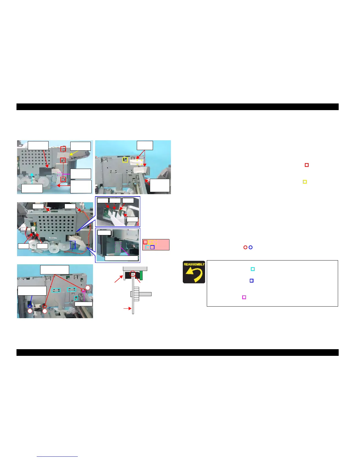
4.4.12 Main Board Unit/Card Slot Unit
External view (1)
Figure 4-23. Removing Main Board Unit (1)
Part/Unit
that should be removed before removing Main Board Unit
Document Cover / Panel Unit / Scanner Unit / Housing, Upper / Housing, Lower
Removal procedure
Main Board Removal
1. Remove the Head FFC Cover (x1) that secures the Head FFCs (x4).
2. Peel off the acetate tape (x1) that secures the PG Sensor Connector Cable.
3. Release the PG Sensor Connector Cable from the tabs (x3, ) of the Main
Board Unit.
4. Peel off the acetate tapes (x2) that secure the PE Sensor Connector Cable, and
release the PE Sensor Connector Cable from the tabs (x2, ) of the Main
Board Unit.
5. Disconnect the following connector cables and FFCs from the connectors of
the Main Board.
• CN3: PE Sensor Connector Cable
• CN4: PG Sensor Connector Cable
• CN5: Head FFC
• CN6: Head FFC
• CN7: Head FFC
• CN8: CR Motor Connector Cable
• CN9:PF Motor Connector Cable
• CN17: Head FFC
6. Remove the screws (x3, ) that secure the Main Board Unit, and remove
the Main Board Unit from the Printer Mechanism.
PG Sensor
Connector
Cable
Head FFC
Cover
Main Board
Unit
Acetate
Tapes
Double-
sided Tape
Acetate
Tapes
PE Sensor
Connector
Cable
CN4CN3
CN8CN9
3
2
1
C.B.S. 3x6 F/Zn
(7±1kgfcm)
Guide Pin
C.B.S. 3x6 F/Zn
(4±1kgfcm)
Slit
PF Encoder
Sensor
PF Scale
Bottom
Double-sided Tape
Tabs
Ribs
CN7
CN6
CN17 CN5
Insert the PF Scale into the slit of the PF Encoder Sensor.
Insert the ribs (x3, ) of the Main Frame into the tabs (x3) of the
Main Board Unit.
Insert the
rib (x1, ) of the Main Board Unit into the tab (x1) of
the Main Frame.
Ma
tch the positioning hole (x1) of the Main Board Unit with the
guide pin (x1, ) of the Main Frame.
Tighten the screws in the order as shown in the figure.
 Loading...


