EPSON Stylus CX4900/CX4905/CX5000/DX5000/DX5050/CX5900/CX6000/DX6000/DX6050 Revision A
DISASSEMBLY/ASSEMBLY Printer Section 157
4.4.21 Paper Guide Upper Unit
External view
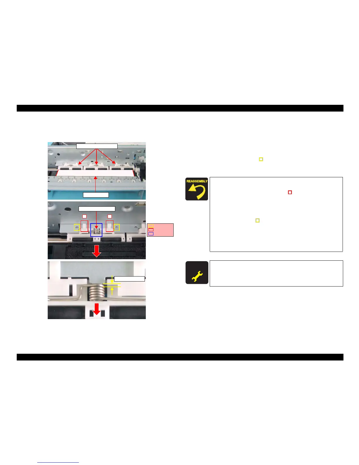
Figure 4-42. Removing Paper Guide Upper Unit
Part/Unit
that should be removed before removing Paper Guide Upper Unit
Document Cover / Panel Unit / Scanner Unit / Housing, Upper / Housing, Lower /
Main Board Unit / CR Guide Frame / CR Motor / CR Scale / Carriage Unit
Removal procedure
1. Set a transparency sheet.
2. Release the guide pins (2 each, ) that secure the Paper Guide Upper Unit
(x3), and remove the Paper Guide Upper Unit (x3) along with Torsion Spring
75.35 (1 each) from the Main Frame.
Transparency
Paper Guide Upper Unit
12
Torsion Spring 75.35
Guide Pins
Tabs
Rib
Approx. 1~1.5mm
Reassembly of the Paper Guide Upper Unit
1. Set Torsion Spring 75.35 onto the Paper Guide Upper Unit.
2. Temporarily place the tabs (x2, ) of the Paper Guide
Upper
Unit onto the Main Frame in order as shown in the
figure.
3. Insert the coil section of Torsion Spring 75.35 into the rib.
4. Align the positioning holes (x2) of the Main Frame
with the
guide pins (x2, ) of the Paper Guide Upper Unit, and set
the Paper Guide Upper Unit al
ong with Torsion Spring
75.35.
5. Pull the coil section of Torsion Spring 75.35 toward you,
hold the margin at approximately 1~1.5 mm, and eliminate
the gap with the Paper Guide Upper Unit.
A D J U S T M E N T
R E Q U I R E D
After removing/replacing the Paper Guide Upper Unit, perform the
adjustment referring to Table 5-1."Required Adjustments" (p172)
 Loading...


