Confidential
Disassembly/Reassembly Overview 9
Epson Stylus Photo R3000 Revision A
1.1 Overview
This chapter describes procedures for disassembling the main parts/units of Stylus Photo R3000. Unless
otherwise specified, disassembled parts/units can be reassembled by reversing the disassembly procedure. See
the cautions or tips for disassembly/reassembly described in “1.3 Detailed Disassembly/Reassembly Procedure
for each Part/Unit (p19)”.
Read the “Safety Precautions (p3)” before disassembling and reassembling.
When you have to remove units or parts that are not described in this chapter, see the exploded diagrams of SPI
(Service Parts Information).
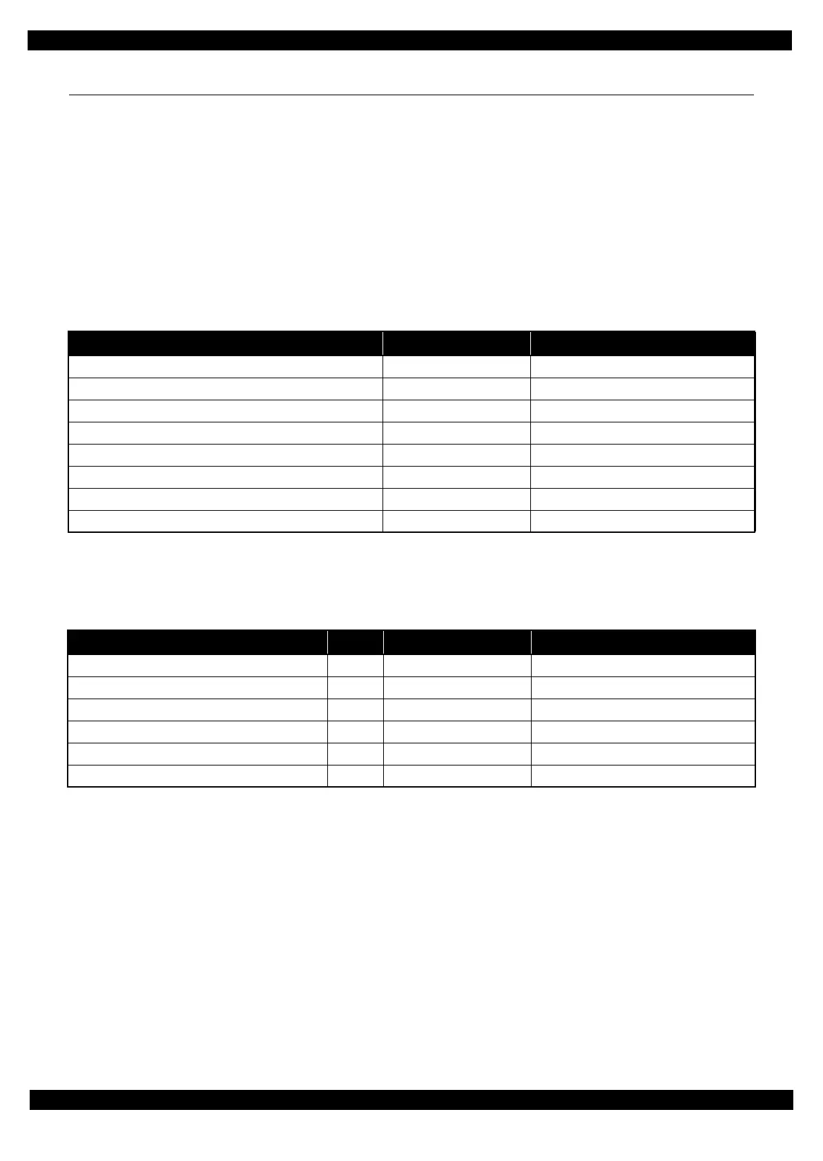
1.1.1 Tools
Use only specified tools to avoid damaging the printer.
Note *1: Some of the tools listed above are commercially available.
*2: EPSON provides the tools listed with EPSON part code.
1.1.2 Jigs
Note *1: The jigs above are used for adjustment (See Chapter 2 “ Adjustment (p32)”.) No jigs are required for disassembling/
reassembling this printer.
*2: Some of the tools listed above are commercially available.
Name Availability
*1
EPSON Part Code
*2
(+) Phillips screwdriver #1 O 1080530
(+) Phillips screwdriver #2 O ---
Flathead screwdriver O ---
Flathead Precision screwdriver #1 O ---
Tweezers O ---
Longnose pliers O ---
Acetate tape --- 1003963
Nippers O ---
Name
*1
Q’ty Availability
*2
EPSON Part Code
Sonic tension gauge 1 --- 1294120
PF roller shaft position adjustment jig 1 --- TBD
Level block 1 --- 1304994
Adjustment gauge for PG adjustment 1 --- 1276333
Tester 1 O ---
Calibrator (i1 Basic UV-Cut) 1 O ---

 Loading...


