Rev.B Overview of Electric Circuits Appendix F-3
TM-L90 Service Manual
Confidential
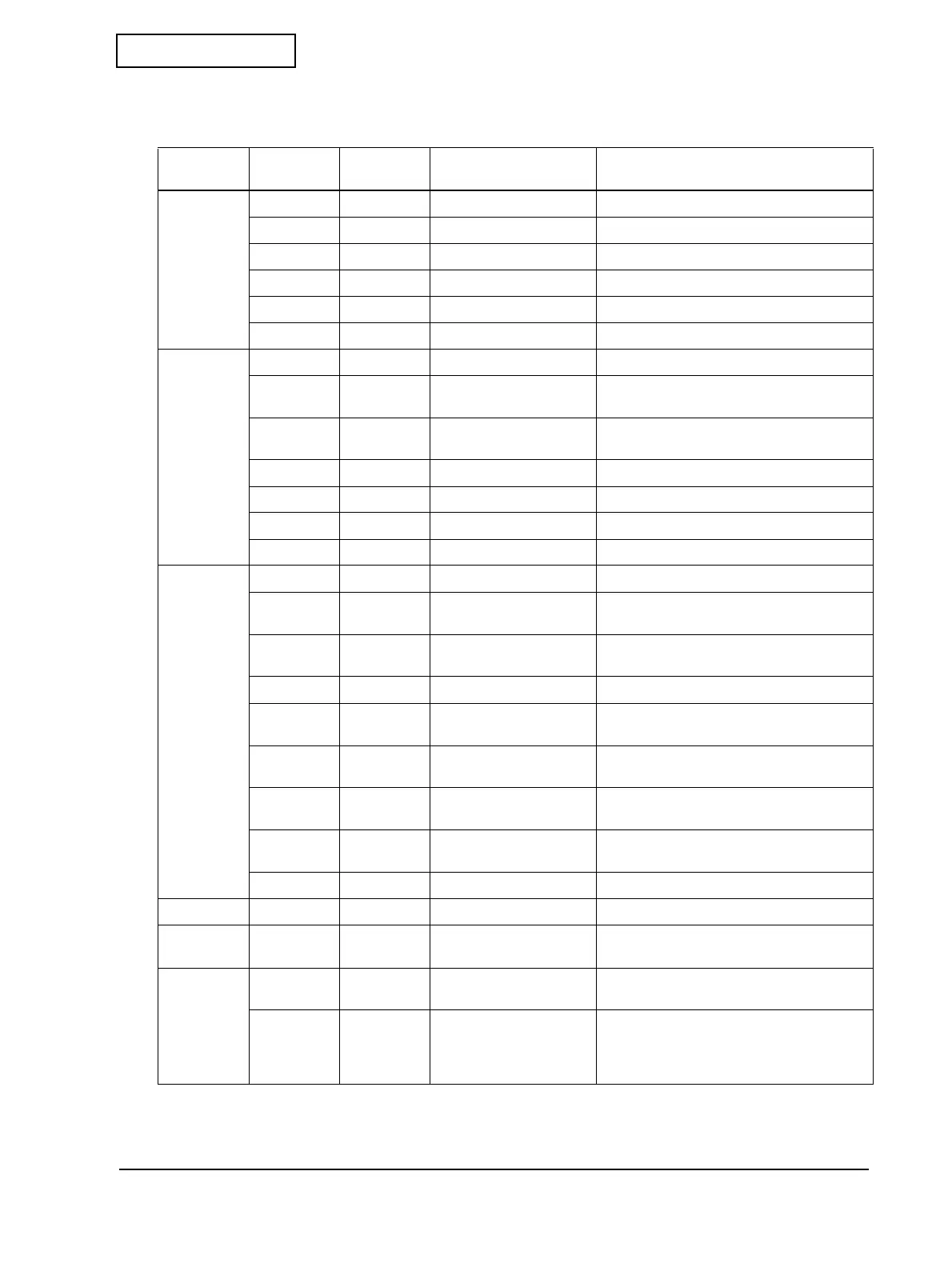
The table below lists the main elements of the main circuit board unit and their functions.
Table F-1 Main elements and their functions for main circuit board unit
Block Location
Signals on
diagram Description Functions
CPU and
peripherals
U4 — —
CPU and custom logic I/O ports
U7 — max 8M bit (512K*16 bit)
Program memory
U8 — 4M bit (256K*16 bit) DRAM
U9 — 8M bit (512K*16 bit)
Font Memory
X1 — 40 MHz
System clock (for U4)
X2 — 25 MHz
System clock (for U4)
Power
supply
system
F1 154004T 4A, surge-proof Printer power supply fuse
Q1 +24V 24 VDC, 1.7A
Semiconductor switch for power supply to
mechanism
QS1, QS2 +24V OUT 24 VDC, 1.7A
Semiconductor switch for power supply to
printer
U1K DKP 24 VDC, 1A
Power supply to drawer
LH9 VH 2 Power supply for thermal head
UZ1 VIO 5 VDC, 1.5A
Power supply to I/O logic circuits
UZ2 VBUS 3.3 VDC, 0.15A
Power supply to bus logic circuits
Connectors
CN6 I/F BOARD —
Universal interface board (UIB) connector
CN10 HEAD — Connector for thermal head unit
connection (front of the printer)
CN11 NE — Connector for paper near-end
connection
CN12 RE — (for TM-T90 only)
CN13 Label photo — Connector for transmission sensor photo
connection
CN4 SUB — Connector for sub circuit board
connection
CN7 SWITCH — Connector for switch circuit board
connection
CN8 A/C — Connector for autocutter unit connection
(front of the printer)
CN9 PF — Connector for PF motor connection
Switch SW1 — — Power switch (front of the printer)
Interfaces
QK2, QK3 DKD 1,
DKD 2
24 VDC, 1A
Drawer drive transistor output signal
Mechanism
drivers
QMA1 ACM+,
ACM-
24 VDC, 0.25A
Driver and output signal for push-pull cutter
motor
UP1, UP2 PF_A+,
PF_A-,
PF_B+,
PF_B-
24 VDC, 0.7A
Driver and output signal for PWM power
supply control of bipolar stepping motor
for feed mechanism
 Loading...