Rev.C Disassembly and Assembly 3-3
TM-L90 Service Manual
Confidential
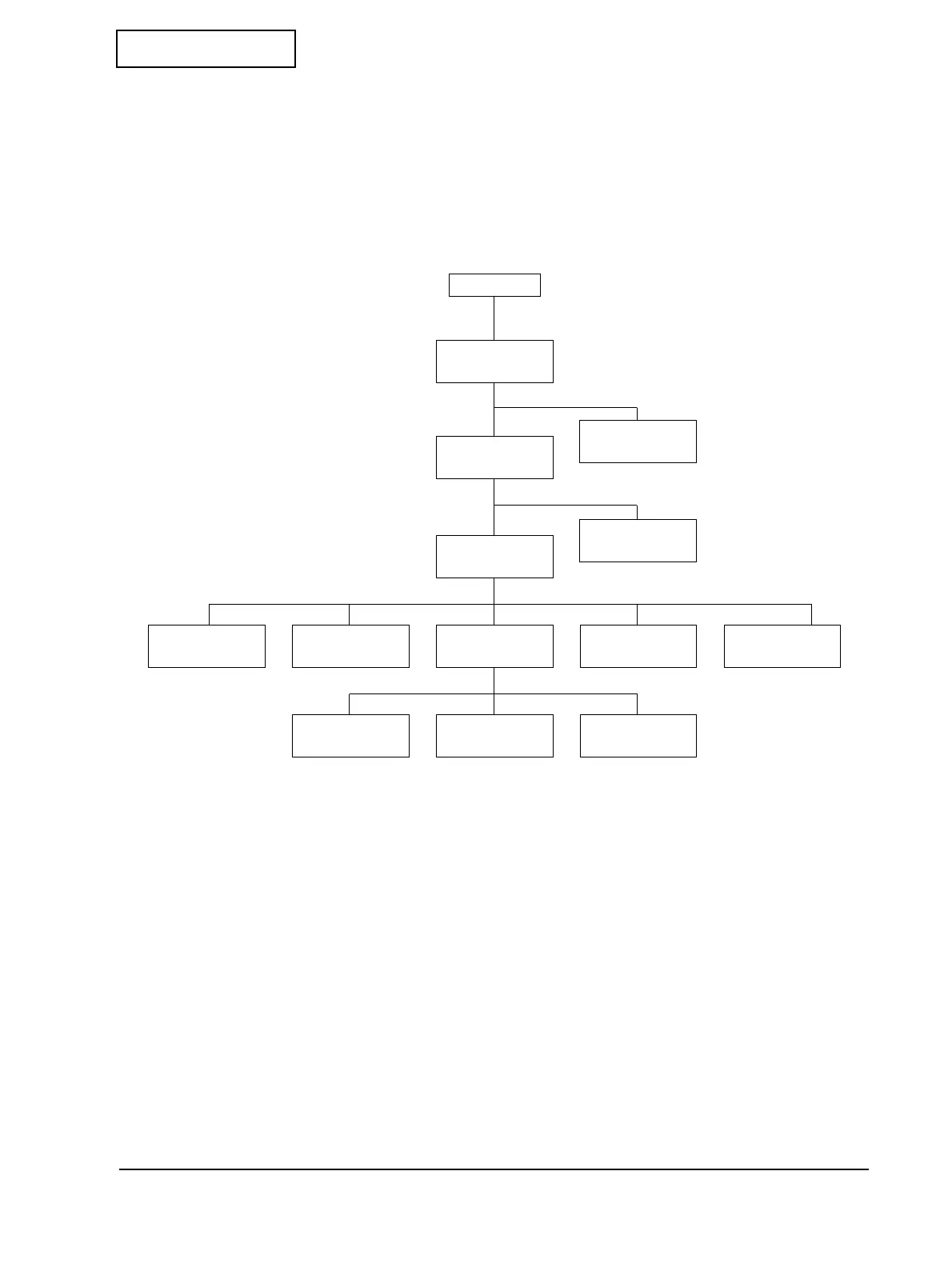
Shortest Route for Disassembly of Major Parts
The next diagram shows the shortest disassembly route of major parts. Perform disassembly by
following this diagram as well as explanations for the target item. For the disassembly
procedure of the thermal print head, see page 3-4.
Representation of Small Parts
The standard small parts used in this chapter (such as screws, washers, and nuts) are all
indicated with abbreviations. For details, see Appendix D, “Parts List.”
Cutter cover
Connector
cover
Thermal print
head assembly
I/F circuit board
unit
Main assembly
case
Main circuit
board unit
Switch circuit
board assembly
Auto cutter unit
N.E. detector
assembly
Paper feed
motor
Sub circuit board
assembly
Cover detector
assembly
Label paper
holder
Start
 Loading...