3
GB
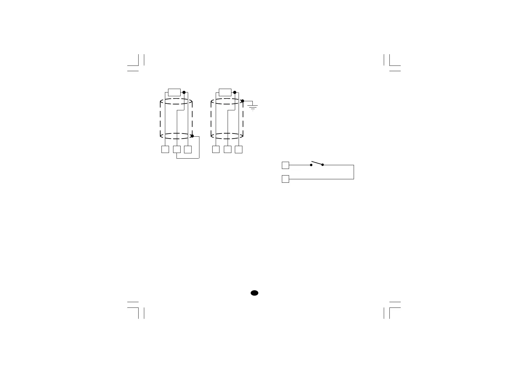
RTD INPUT
Fig. 4 RESISTANCE TEMPERATURE
DETECTOR CONNECTION
NOTES:
1) Do not run input wires together with power line
cables.
2) Pay attention to the line resistance; a resistance
higher than 20 Ω/wire may cause measurement
errors.
3) When shielded cable is used, it should be
grounded at one side only to avoid ground loop
currents.
4) The impedence of the 3 wires must be the
same.
8
RTD
10
9 8
RTD
10
9
11
12
Log. input 2
LOGIC INPUT
Safety note:
1) The "OUT 3" and the "logic input" options are
mutually exclusive.
2) Do not run logic input wiring together with
power cables.
3) Use an external dry contact capable of
switching 8 mA, 8 V DC.
4) The instrument needs 300 ms to recognize a
contact status variation.
5) The logic input is NOT isolated by the
measuring input
Fig. 5 - LOGIC INPUT WIRING
The logic input can be programmed as:
A) Set point selector
A.1) In this case it will operate as follows:
logic input operat. set point
open SP
close SP2
B) Start timer
In this case it will operate as described at
paragraph 5.10 (Timer modes description).
lxe-1-B00.p65 10/18/02, 3:46 PM3