25
GB
- The instrument is set to use two control outs and
an UNDERRANGE is detected, OUT 1 turns ON
and OUT 2 turns OFF.
For inputs from thermocouple the underrange
indication can be selected as shown in section 7.2
of this manual.
NOTE: When an
overrange
or an
underrange
is
detected, the alarms operate as if the
instrument had detected the maximum or
the minimum measurable value
respectively.
To eliminate the out of span condition, proceed as
follows:
1) Check the input signal source and the
connecting line.
2) Make sure that the input signal is in
accordance with the instrument configuration.
Otherwise, modify the input configuration (see
section 4).
3) If no error is detected, send the instrument to
your supplier to be checked.
6. ERROR MESSAGES
6.1 MEASUREMENT ANOMALY SIGNAL
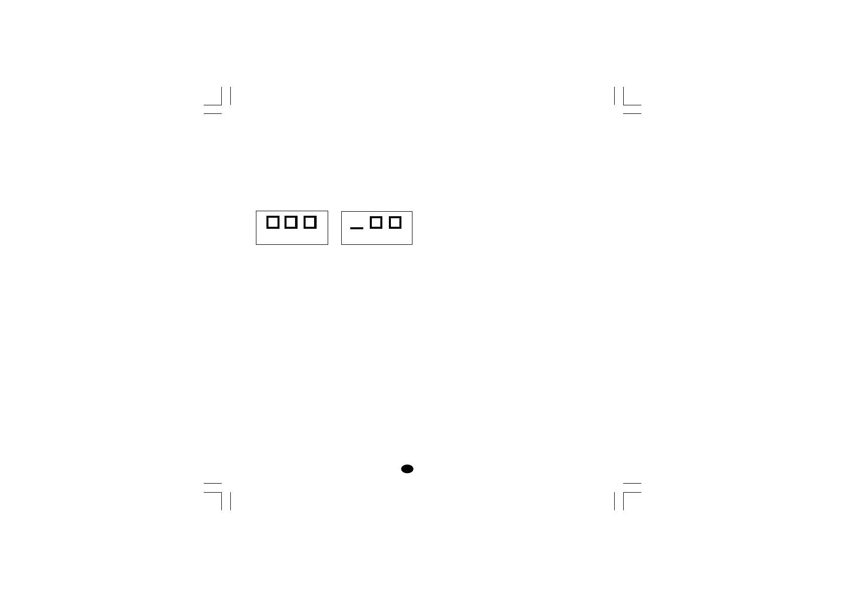
The instrument display (the upper display for
model LME) shows the OVERRANGE and
UNDERRANGE conditions with the following
indications:
Overrange Underrange
The example shows the display of model LME.
Model LDE displays 4 digits.
The sensor break can be signalled as:
- for TC/mV input : OVERRANGE or
UNDERRANGE selected
by a solder jumper
- for RTD input : OVERRANGE
On RTD input, a special test is provided to signal
OVERRANGE when input resistance is less than
12 ohm (Short circuit sensor detection).
NOTE:
When:
- The instrument is set for one control out only and
an OVERRANGE is detected, the OUT 1 turns
OFF (if reverse action) or ON (if direct action).
- The instrument is set to use two control outs and
an OVERRANGE is detected, OUT 1 turns OFF
and OUT 2 turns ON.
- The instrument is set for one control out only and
an UNDERRANGE is detected, the OUT 1 turns
ON (if reverse action) or OFF (if direct action).
lxe-1-B00.p65 10/18/02, 3:47 PM25