2
GB
MEASURING INPUTS
NOTE: Any external components (like zener
barriers etc.) connected between sensor and input
terminals may cause errors in measurement due
to excessive and/or not balanced line resistance or
possible leakage currents.
TC INPUT
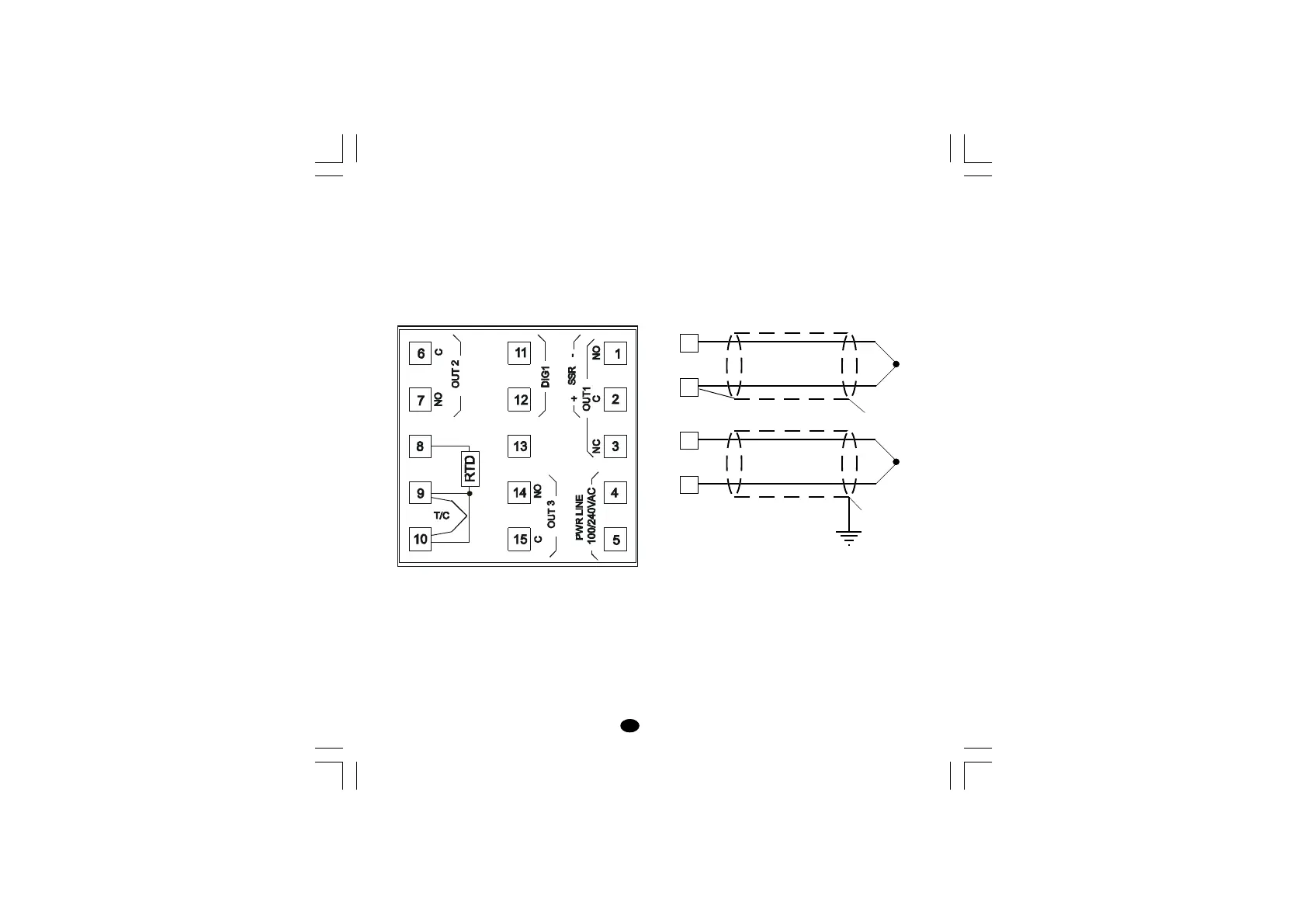
Fig. 3 THERMOCOUPLE CONNECTION
NOTES:
1) Do not run input wires together with power line
cables.
2) For TC wiring use proper compensating cable
preferably shielded.
3) When a shielded cable is used, it should be
connected at one point only.
2. ELECTRICAL CONNECTIONS
Connections are to be made with the instrument
housing installed in its proper location.
Fig. 2 REAR TERMINAL BLOCK
10
9
+
_
10
9
+
_
Shield
Shield
+
-
lxe-1-B00.p65 10/18/02, 3:46 PM2