5
GB
In every case the cable connected to the relay
outs must be routed as far away as possible from
input or communication cables.
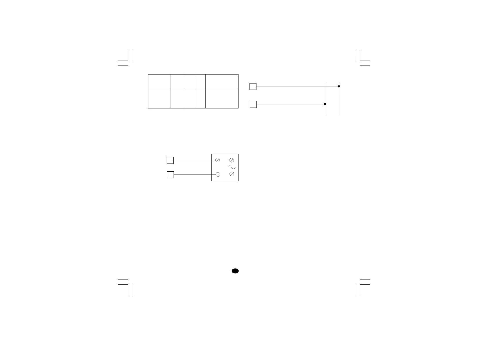
VOLTAGE OUTS FOR SSR DRIVE
Fig. 8 SSR DRIVE OUT WIRING
It is a time proportioning out.
Logic level 0: Vout < 0.5 V DC.
Logic level 1: Maximum current = 20 mA.
- 14 V + 20 % @ 20 mA
- 24 V + 20 % @ 1 mA.
NOTE: This out is NOT isolated.
A double or reinforced Isolation between instrument
output and power supply must be assured by the
external solid state relay.
LOAD
(mA)
<40 mA
<150 mA
<0.5 A
C
(mF)
0.047
0.1
0.33
R
(W)
100
22
47
P.
(W)
1/2
2
2
OPERATING
VOLTAGE
260 V AC
260 V AC
260 V AC
+
_
_
+
2
1
OUT 1
SOLID STATE
RELAY
POWER LINE WIRING
Fig. 9 POWER LINE WIRING
NOTES:
1) Before connecting the instrument to the supply,
make sure that the line voltage corresponds to
that indicated on the rating plate.
2) To avoid electric shock, connect the power line at
the end of the wiring procedure.
3) For supply connections use No 16 AWG or larger
wires rated for at least 75°C.
4) Use copper conductors only.
5) Do not run input wires together with power line
cables.
6) For 24 V AC/DC the polarity does not matter.
7) The power supply input has NO fuse protection.
Please, provide a T type 1A, 250 V fuse externally.
8) The safety regulations for equipment
permanently connected to the mains require
that there is a switch or circuit breaker in the
building electrical system and that this:
- is near the device and can easily be reached by
the operator;
- is marked as the device ON/OFF device.
NOTE: A single switch or circuit-breaker can drive
more than one instrument.
4
R (S,T)
R (S,T)
N
5
N
Power Line
100 V to 240 V AC (50/60Hz)
or 24 V AC/DC
lxe-1-B00.p65 10/18/02, 3:46 PM5