
N
nancy00Aug 30, 2025
What does 'Tip Saver Fault' mean on ESAB 200i Welding System?
- AadamsbrianAug 30, 2025
The 'Tip Saver Fault' on the ESAB Welding System indicates that the tip remained in contact with the work for more than 15 seconds.
What does 'Tip Saver Fault' mean on ESAB 200i Welding System?
The 'Tip Saver Fault' on the ESAB Welding System indicates that the tip remained in contact with the work for more than 15 seconds.
What to do if the ESAB 200i displays 'Inverter 3A Output Current High'?
If the ESAB Welding System displays 'Inverter 3A Output Current High', it indicates that the plasma work current is high during cutting and attributed to Inverter Module 3 Section A output being high. If the problem persists, replace Inverter Module 3.
What does 'Work Current Too High' mean on ESAB 200i?
If the ESAB Welding System displays 'Work Current Too High', it means the work lead current detected is greater than 16% above the process setting. Possible causes include a defective HCT1 work lead current sensor or Relay PCB, or a defective CCM.
What to do if the ESAB Welding System displays 'AC Voltage Low'?
If the ESAB Welding System displays 'AC Voltage Low', it means the System Bias PCB detected that the AC voltage is lower than the power supply's rated voltage. Check for a damaged or disconnected System Bias Supply J61 voltage selection connection, a defective System Bias PCB, or a defective CCM.
What to do if the ESAB Welding System displays 'Inverter 1 Not Found'?
If the ESAB Welding System displays 'Inverter 1 Not Found', remember that Inverter Module 1 Section A is required for piloting. Check the ribbon cable connection from CCM J31 to Inverter Module 1 Section A.
What to do if the ESAB 200i displays 'Inverter 3B Incompatible Revision'?
If the ESAB Welding System displays 'Inverter 3B Incompatible Revision', it could indicate an unsupported inverter revision. Check the ribbon cable from CCM J36 to Inverter Module 3 Section B for damage. It's also possible that the CCM code version is incompatible with the inverter revision or model.
What to do if the ESAB 200i displays 'BIAS VAC Invalid'?
If the ESAB Welding System displays 'BIAS VAC Invalid', it could be due to an invalid AC voltage selection, a damaged or loose connection at J61 of the System Bias Supply, or a defective System Bias PCB. Check these components and connections.
How to fix coolant leaks in my ESAB Welding System?
If you're experiencing coolant leaks in your ESAB Welding System: * Check for damaged or punctured coolant lines and replace them. * Ensure the supply and return hoses are not reversed. Match coolant connection colors to the arc starter fitting colors.
What to do if the ESAB Welding System displays 'DC Output Low'?
If your ESAB Welding System displays 'DC Output Low', and the voltage is less than 60 VDC, there may be a negative lead short to work or ground. Other potential causes include a defective inverter (output shorted), a disconnected or broken CCM voltage sense (J24) wire, or a defective CCM. Check these components to troubleshoot the issue.
What causes ESAB 200i Welding System to show 'Pilot Ignition Failure'?
If you're experiencing 'Pilot Ignition Failure' with your ESAB Welding System, it could be due to worn torch consumable parts. Ensure the correct process is selected, or manual settings, including the current control setting, match the consumables. Also, check for high plasma pressure, a defective arc starter, a defective Pilot PCB, or a defective Inverter section 1A. Verify that the ribbon cables are correctly connected on INV1 sections 1A and 1B.
Essential safety precautions for English-speaking users.
Safety precautions provided in French Canadian for user protection.
Technical specifications and electrical requirements for different system amperages.
Specifies the required gases, quality, pressure, and flow rates for system operation.
Outlines electrical, gas, and water supply requirements for installation.
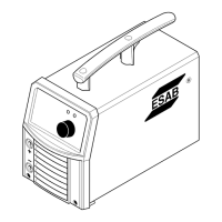
Provides instructions and warnings for safely lifting the power supply unit.
Step-by-step guide for connecting input power and system ground cables.
Instructions for connecting the work cable, pilot, and negative leads.
Procedures for establishing proper grounding to minimize EMI and ensure safety.
Instructions for connecting the color-coded coolant hoses to the power supply.
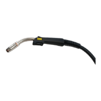
Step-by-step instructions for connecting the plasma torch assembly to the leads.
Procedure for installing torch consumables to ensure proper operation and seating.
Explains the indicators and functions on the power supply control panel.
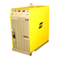
Contains operating information specific to the power supply, including startup sequences.
Lists and explains CCM status codes indicating active faults or conditions.
Troubleshooting guide for common symptoms and causes related to the Remote Arc Starter.
Periodic checks recommended for power supply maintenance to ensure performance.
Steps for cleaning the external coolant filter to maintain optimal coolant flow efficiency.
Detailed steps for draining and replacing the coolant in the system.
Procedure for removing consumables from the torch cartridge assembly.
Steps for installing torch consumables to ensure proper operation and seating.
Troubleshooting guide for identifying and resolving coolant leaks from the torch head.
Cutting data for mild steel, O2 plasma/shield, up to 100 amps.
Cutting data for bevel and robotic operations up to 100 amps.
Cutting data for mild steel, O2 plasma/shield, 150-200 amps.
Cutting data for robotic and bevel operations, 150-200 amps.
Cutting data for mild steel, O2 plasma/shield, 250-300 amps.
Cutting data for robotic and bevel operations, 250-300 amps.
Cutting data for mild steel, O2 plasma/shield, 400 amps.
Cutting data for robotic and bevel operations, 400 amps.
Procedure for installing consumables into the torch cartridge assembly.
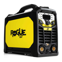
| Input Voltage | 230 V |
|---|---|
| Current Range | 5 - 200 A |
| Input Current | 16 A |
| Output Current Range | 5 - 200 A |
| Efficiency | 85% |
| Process | MMA/TIG |