EasyManua.ls Logo

ESAB Cutmaster 120 - User Manual

ESAB Cutmaster 120
76 pages
Print Icon
To Next Page IconTo Next Page
Loading...
120
Art # A-12769_AB
208/230V
400V
460V
Revision: AB Issue Date: April 15, 2015 Manual No.: 0-5380
ESAB Cutmaster
®
120
PLASMA CUTTING SYSTEM
SL100 1Torch™
Operating
Manual
esab.com.br

Table of Contents

Questions and Answers

  • R
    Robert MedinaSep 14, 2025
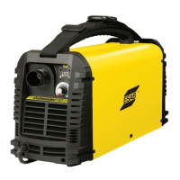
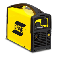
    Why are the FAULT and 70 PSI indicators flashing on my ESAB Welding System?
    • S
      Sandra ButlerSep 14, 2025
      If the FAULT and 70 PSI indicators are flashing on your ESAB Welding System, here's what you should check: 1. Make sure the shield cup is hand-tightened until it is snug. 2. Ensure the torch ATC is securely fastened to the unit. 3. If there is a problem in the torch and leads PIP circuit, replace the torch and leads or return to an authorized service center for repair or replacement. 4. If none of the above steps resolve the issue, it could be due to failed components in the unit, requiring a return to an authorized service center for repair or replacement.
  • J
    julia97Sep 12, 2025
    What to do if FAULT and 75 PSI indicators are flashing on my ESAB Welding System?
    • J
      Jennifer JuarezSep 12, 2025
      If the FAULT and 75 PSI indicators are flashing on your ESAB Welding System, it means that: * The start signal is active when the ON/OFF switch is turned to the ON position. The start can be active if the hand torch switch or hand pendant switch is held closed, or if the CNC START signal is active low. Release the START signal source. * There is a problem in the torch and leads switch circuit. Replace the torch and leads or return to an authorized service center for repair or replacement. * There are failed components in the unit. Return to authorized service center for repair or replacement.
  • C
    Claire OwenSep 12, 2025
    How to troubleshoot an ESAB Welding System when the ON/OFF switch is ON, but the A/C Indicator does not light?
    • R
      Roy GregorySep 12, 2025
      If the ON/OFF switch is in the ON position, but the A/C indicator light doesn't illuminate on your ESAB Welding System, here's what to check: 1. Ensure the primary power disconnect switch is in the ON position. 2. Have a qualified person check the primary fuses/breakers. Also, try connecting the unit to a known good primary power receptacle. 3. Replace the internal fuse. If it blows again, return the unit to an authorized service center. 4. If none of the above steps work, there may be faulty components in the unit. In that case, return it to an authorized service center for repair or replacement.
  • J
    Janice LiuSep 10, 2025
    How to fix ESAB Cutmaster 120 if ON / OFF Switch is ON but the A/C Indicator does not light?
    • B
      bridgetwalshSep 10, 2025
      If the ON / OFF Switch is ON but the A/C Indicator does not light, try the following: - Turn the primary power disconnect switch to the ON position. - Have a qualified person check the primary fuses/breakers, and connect the unit to a known good primary power receptacle. - Replace the fuse. If the fuse blows again, return the unit to an authorized service center for repair or replacement.
  • H
    Henry KelleySep 9, 2025
    What to do if FAULT and 85 PSI indicators are flashing on ESAB Cutmaster 120?
    • K
      Kenneth WhiteSep 9, 2025
      Turn the ON / OFF switch OFF then back ON again. If that does not clear the fault, return to an authorized service center for repair.
  • T
    Terrence JonesAug 23, 2025
    What to do if GAS LED is OFF, and FAULT and MIN pressure indicators are flashing on my ESAB Cutmaster 120?
    • J
      Joseph TranAug 23, 2025
      If the GAS LED is off and the FAULT and MIN pressure indicators are flashing on your ESAB Cutter, the possible causes are: 1. The gas supply is not connected to the unit (connect gas supply). 2. The gas supply is not turned on (turn the gas supply on). 3. The gas supply pressure is too low (set air supply inlet pressure to unit to 120 psi). 4. The AIR PRESSURE CONTROL regulator is set too low. If none of these steps resolve the issue, the problem may be failed components in the unit.
  • E
    Eric PattersonSep 7, 2025
    What to do if FAULT and 70 PSI indicators are flashing on my ESAB Cutter?
    • W
      winterslisaSep 7, 2025
      If the FAULT and 70 PSI indicators are flashing: - Hand tighten the shield cup until it is snug. - Ensure the torch ATC is securely fastened to the unit.
  • L
    Laura HughesSep 6, 2025
    What to do if FAULT and 80 PSI indicators are flashing and gas flow is cycling ON and OFF on ESAB Cutmaster 120 Cutter?
    • D
      Daniel RodriguezSep 6, 2025
      If the FAULT and 80 PSI indicators are flashing and the gas flow is cycling ON and OFF: - Tighten the shield cup by hand, but do not overtighten. - Turn OFF the power supply, remove the shield cup, and install any missing parts. - Turn OFF the power supply, bleed down the system pressure, remove the shield cup, tip, and start cartridge, and check the start cartridge lower end fitting for free movement. Replace the fitting if it does not move freely.
  • C
    Christine KimSep 5, 2025
    What to do if FAULT and 75 PSI indicators are flashing on ESAB Cutmaster 120?
    • D
      dawn13Sep 5, 2025
      If the FAULT and 75 PSI indicators are flashing: - The start can be active because the hand torch switch or hand pendant switch is held closed, or the CNC START signal is active low. Release the START signal source.
  • S
    Stephanie SullivanSep 4, 2025
    What to do if GAS LED is OFF, and FAULT and MIN pressure indicators are flashing on ESAB Cutter?
    • N
      nicholas05Sep 4, 2025
      If the GAS LED is OFF, and the FAULT and MIN pressure indicators are flashing: - Connect the gas supply to the unit. - Turn the gas supply ON. - Set the air supply inlet pressure to the unit to 120 psi. - Adjust the regulator to set the air pressure.

Summary

ESAB Cutmaster 120 Plasma Cutting System

SECTION 1: SAFETY

1.0 Safety Precautions

Details crucial safety measures, personal protective equipment, and general precautions to ensure safe operation.

Critical Safety Warnings

SECTION 2 SYSTEM: INTRODUCTION

How To Use This Manual

Explains how to navigate and interpret the operating manual, including understanding warnings and notes.

Power Supply Specifications

Input Wiring Specifications

SECTION 2 TORCH: INTRODUCTION

Torch Specifications

Details technical specifications for torch configurations, lead lengths, parts, and cooling methods.

SECTION 3 SYSTEM: INSTALLATION

Unpacking and Lifting

Guides on unpacking the system components and details safe handling and lifting precautions for the power supply.

Gas Connections and Filters

SECTION 3 TORCH: INSTALLATION

Torch Connections

Instructs on how to properly connect the ESAB SL100 torch to the power supply unit.

SECTION 4 SYSTEM: OPERATION

Front Panel Controls; Features

Identifies and describes the main controls, indicators, and their functions on the front panel of the plasma cutting system.

Operation Preparations and Checks

Torch Parts Selection and Connection

Guides on selecting and connecting the correct torch parts for optimal cutting performance.

Cutting Operation Procedures

Cutting Modes and Arc Control

Explains different cutting modes (RUN, RAPID AUTO RESTART, LATCH) and how to initiate and maintain the cutting arc.

Torch Operation Details

Torch Parts Selection and Cut Quality

Guides on selecting torch parts and explains factors affecting cut quality.

Gouging Operation

Torch Consumable Parts Selection

Recommended Cutting Speeds (Exposed Tip)

Recommended Cutting Speeds (Shielded Tip)

SECTION 5 SYSTEM: SERVICE

5.01 General Maintenance

Outlines the general maintenance schedule and tasks required for the plasma cutting system.

Basic Troubleshooting Guide

SECTION 5 TORCH: SERVICE

5 T.01 General Maintenance

Provides guidance on cleaning the torch and lubricating O-rings for optimal performance.

SECTION 6: PARTS LISTS

Ordering Information

Provides instructions on how to order replacement parts by catalog number and includes return policy information.

APPENDIX 1: SEQUENCE OF OPERATION (BLOCK DIAGRAM)

APPENDIX 4: TORCH CONNECTION DIAGRAMS

APPENDIX 5: SYSTEM SCHEMATIC, 208;460 V UNITS

ESAB Cutmaster 120 Specifications

General IconGeneral
BrandESAB
ModelCutmaster 120
CategoryCutter
LanguageEnglish

Related product manuals