CUTMASTER A60
INSTALLATION 0-5428
3-4
9. Connect the opposite end of individual wires to
a customer supplied plug or main disconnect.
10. Connect the input power cable (or close the main
disconnect switch) to supply power.
3.06 Gas Connections
Connecting Gas Supply to Unit
The connection is the same for compressed air or high
pressure cylinders. Refer to the following subsections
if an optional air line lter is to be installed.
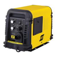
1. Connect the air line to the inlet port. The illustra-
tion shows typical ttings as an example.
NOTE!
For a secure seal, apply thread seal-
ant to the tting threads, according
to the manufacturer's instructions.
Do Not use Teon tape as a thread
sealer, as small particles of the tape
may break off and block the small air
passages in the torch.
Art # A-08320
Inlet Po
Hose Clamp
1/4 NPT or ISO-R
Air Connection to Inlet Port
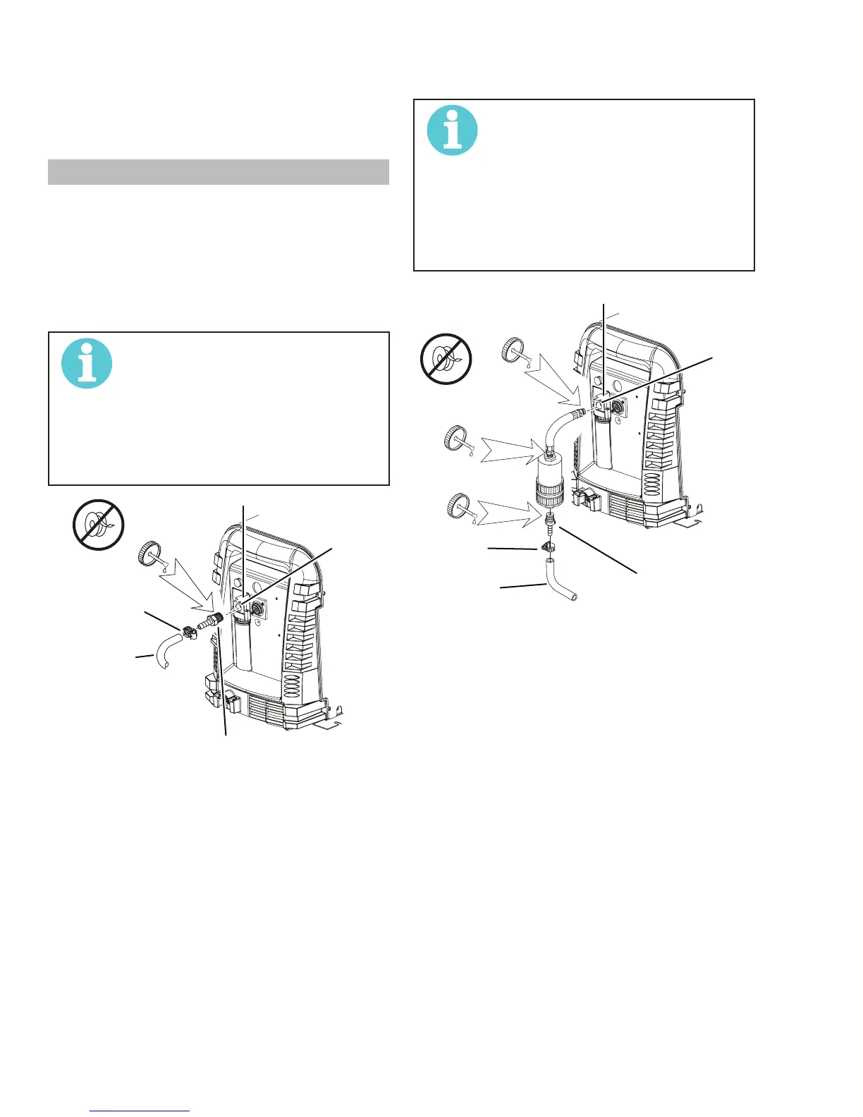
Installing Optional Single - Stage Air Filter
An optional lter kit is recommended for improved lter-
ing with compressed air, to keep moisture and debris
out of the torch.
1. Attach the Single - Stage Filter Hose to the Inlet
Port.
2. Attach the Filter Assembly to the lter hose.
3. Connect the air line to the Filter. The illustration
shows typical ttings as an example.
NOTE!
For a secure seal, apply thread seal-
ant to the tting threads, according
to the manufacturer's instructions.
Do Not use Teon tape as a thread
sealer, as small particles of the tape
may break off and block the small air
passages in the torch. Connect as
follows:
p
1/4 NPT to 1/4"
(6mm) Fitting
Inlet Po
Gas Supply
Hose
Optional Single - Stage Filter Installation
Using High Pressure Air Cylinders
When using high pressure air cylinders as the air supply:
1. Refer to the manufacturer’s specications for
installation and maintenance procedures for high
pressure regulators.
2. Examine the cylinder valves to be sure they are
clean and free of oil, grease or any foreign mate-
rial. Briey open each cylinder valve to blow out
any dust which may be present.
3. The cylinder must be equipped with an adjust-
able high - pressure regulator capable of outlet
pressures up to 100 psi (6.9 bar) maximum and
ows of at least 300 scfh (141.5 lpm).
4. Connect supply hose to the cylinder.