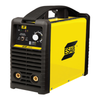
ESAB ES 95i
Manual 0-5458 3-1 INSTALLATION
3.01 Environment
These units are designed for use in environments with increased
hazard of electric shock. Examples of environments with
increased hazard of electric shock are:
A. In locations in which freedom of movement is restricted, so
that the operator is forced to perform the work in a cramped
(kneeling, sitting or lying) position with physical contact
with conductive parts.
B. In locations which are fully or partially limited by conductive
elements, and in which there is a high risk of unavoidable
or accidental contact by the operator.
C. In wet or damp hot locations where humidity or perspiration
considerably reduces the skin resistance of the human body
and the insulation properties of accessories.
Environments with increased hazard of electric shock do not
include places where electrically conductive parts in the near
vicinity of the operator, which can cause increased hazard, have
been insulated.
3.02 Location
Be sure to locate the welder according to the following guide-
lines:
• In areas, free from moisture and dust.
• Ambient temperature between 32°F (0°C) to 104° F (40°
C).
• In areas, free from oil, steam and corrosive gases.
• In areas, not subjected to abnormal vibration or shock.
• In areas, not exposed to direct sunlight or rain.
• Place at a distance of 12” (300mm) or more from walls or
similar that could restrict natural air flow for cooling
WARNING
ESAB advises that this equipment be elec-
trically connected by a qualified electrician.
SECTION 3:
INSTALLATION
3.03 Electrical Input Connections
WARNING
ELECTRIC SHOCK can kill; SIGNIFICANT DC
VOLTAGE is present after removal of input
power.
DO NOT TOUCH live electrical parts.
SHUT DOWN welding power source, disconnect input power em-
ploying lockout/tagging procedures. Lock-out/tagging procedures
consist of padlocking line disconnect switch in open position,
removing fuses from fuse box, or shutting off and red-tagging
circuit breaker or other disconnecting device.
Electrical Input Requirements
Operate the welding power source from a single-phase 60 Hz, AC
power supply. The input voltage must match one of the electri-
cal input voltages shown on the input data label on the unit
nameplate. Contact the local electric utility for information about
the type of electrical service available, how proper connections
should be made, and inspection required. The line disconnect
switch provides a safe and convenient means to completely
remove all electrical power from the welding power supply
whenever necessary to inspect or service the unit.
Do not connect an input (WHITE or BLACK) conductor to the
ground terminal.
Do not connect the ground (GREEN) conductor to an input line
terminal.