Cause Corrective Action
• Voltage should be between 10.8 – 13.2VDC, if 12 VDC SMPS (item code 1080945) is
used.
• If voltage is out of range or no voltage, check connection between SMPS (power
supply) and relay board.
•
Fuse F1 is blown or
circuit is not
energized
• Check that AC voltage is supplied to the Relay board.
• Ensure the Motor Blower FAN button and LED is energized.
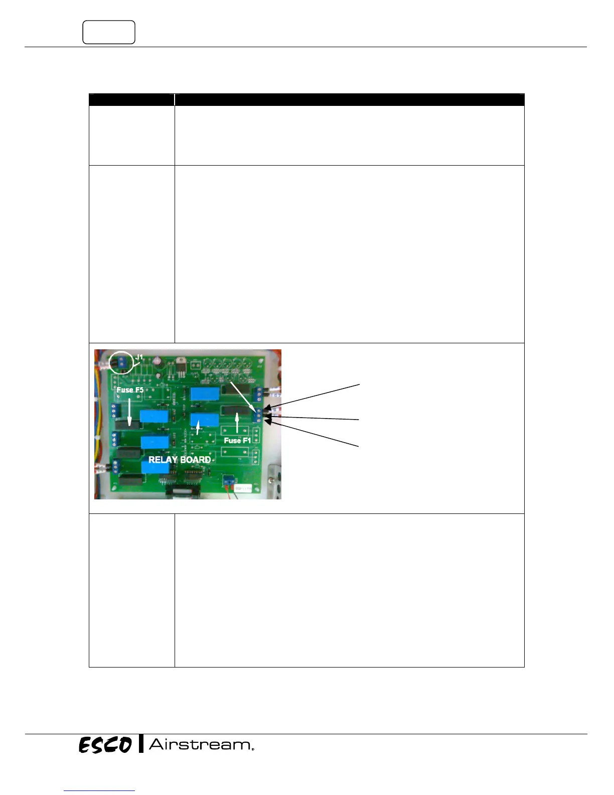
• Locate LS1 circuit and measure AC voltage between large BLUE (Neutral) terminal
block and the end terminal (with Red cable) on the three terminal strips (J2 on relay
board). See Figure 4-1.
• If there is voltage to the end terminal (Terminal with cable) check the central
terminal (Normally Open Circuit) to the BLUE (Neutral) terminal block.
• Should there be no voltage detected at the central terminal, the fuse could have
been blown or the circuit is not energized.
• Check Fuse F1 on relay board. See Figure 4-1.
• If fuse F1 is blown, as temporary solution, use F5 (spare) to replace F1.
• If fuse F1 is good, check the voltage between the BLUE (Neutral) terminal block and
the end terminal on the LS1 circuit (J2 on relay board)
• Detection of voltage at the end terminal with no cable indicates that the F1 fuse is
good and the circuit is not energized.
K1 Relay not
energized or faulty
• Check voltage at the speed control on the motor voltage test points - Refer to
Figure 4-2 (E/S series) and Figure 4-3 (N series).
• If the voltage is correct at the speed control Proceed to the next step. No voltage at
the speed control indicates that K1 relay is not energized or the wiring between the
Relay board and K1 is open.
• Check the voltage between the BLUE (Neutral) terminal block and NO terminal
contact at K1 relay. Refer to Figure 4-4/4-5.
• Ensure that the motor blower switch in front keypad membrane is on.
• If voltage is present at K1, proceed to check the speed controller in next section.
Otherwise, check all terminal connections to K1 relay.
• If connections on K1 relay are OK, visually inspect K1 relay for any burnt or flash
marks. Refer to Figure 4-5.
• If burnt or flash marks are present, replace the relay.
Power in to FAN Circuit
Power out to K1
Normally c
-not used
Relay LS1
Terminal J2