Class II Biological Safety Cabinets
Cause Corrective Action
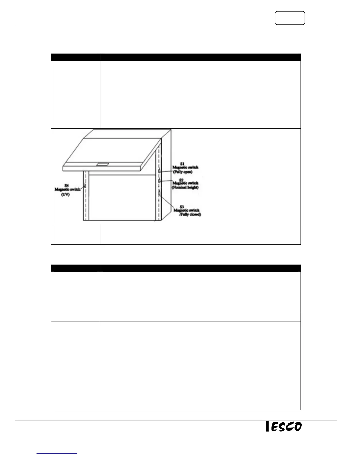
• To access the magnetic switches for the sash positions, remove the right sash
window profile cover as you face the cabinet.
• There are 3 magnetic switches inside the right profile. See Figure 7-2 below. The one
in the middle is for Ready position.
• There is a magnet attached to the glass to activate the magnet.
• Shift the switch or magnet position so the distance between them is between 10-
13mm (3/8 to 1/2”) as explained in Figure 7-2 below. If the distance is too far, the
switch may not be able to detect the magnet.
• If the LCD still displays “SASH: NO!”, the switch may be defective or there is a wiring
connection problem. To check the connections proceed to the next step.
Connection
Problem
• Locate Connector C and D and check male and female side for any bad connection.
• If the fluorescent lamp still does not light with the LIGHT LED ON return to start of
Problem 7 and repeat the troubleshooting process.
Problem 8: UV Light always OFF
Cause Corrective Action
Sash not in UV
state
• Lower the sash to UV mode position.
• If “SASH FULLY CLOSED” is not displayed on the LCD, please refer to the Magnetic
Switch troubleshooting section.
• Switch on the UV lamp by pressing the UV button.
•
If “SASH FULLY CLOSED” is displayed on LCD but UV is not ON after pressing UV
button, refer to the Magnetic Switch troubleshooting section.
Faulty UV tube
• Replace the faulty UV tube.
Faulty UV ballast
• Check incoming voltage to the Relay board.
• Locate LS8 (J15 Terminal) circuit and measure AC voltage between large BLUE
(Neutral) terminal block and the end terminal (with Red cable) on the three terminal
strip (J15 on relay board).
• If there is no incoming voltage to the end terminal (Terminal with cable), refer to the
next step NO power to UV Relay circuit LS8.
• If voltage to the end terminal (Terminal with cable) exists, check the central terminal
(Normally Open Circuit) to the BLUE (Neutral) terminal block.
• Absence of voltage at the central terminal indicates a blown fuse or the circuit is not
energized.
• Check Fuse F8 on relay board. See Figure 8-1 below.
• If fuse F8 is blown, as temporary solution, use F5 (spare) to replace F8.
•
, check the voltage between the BLUE(NEUTRAL) terminal block and