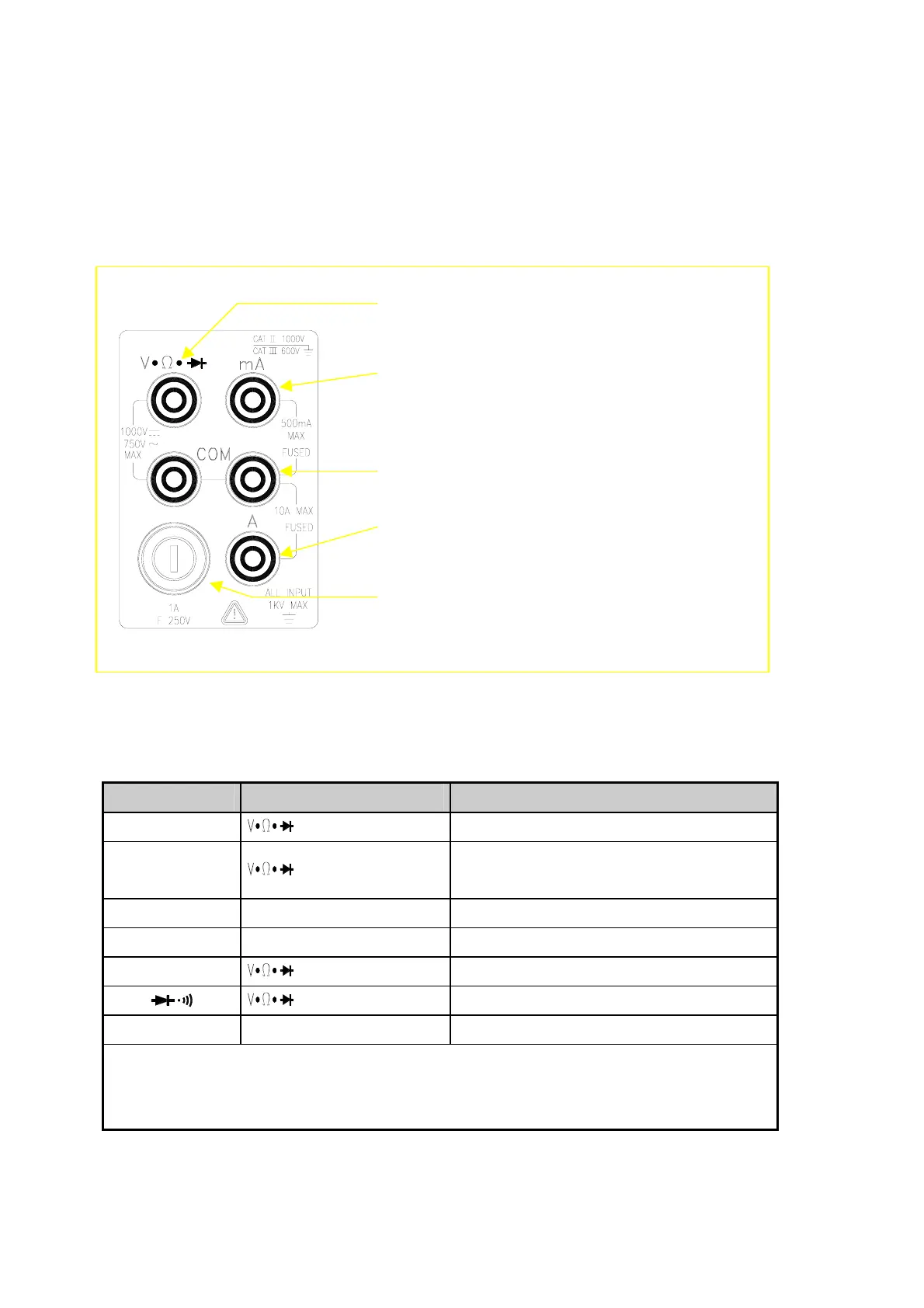
3-4 Input Terminals
The input terminals, shown in Figure 3-2 are located on the left side of the
front panel. The meter is protected against overloads up to the limits shown in
Table 3-1. Exceeding these limits poses a hazard to both the meter and
operator.
Input-High Terminal for Volts, Ohms, Hz,
Diode/Continuity Measurements
500
µ
A~500mA Range DC/AC Current Input
Terminal for DC/AC Current Measurement
Common Terminal (COM)
5A/10A Range Current Input Terminal for DC/AC
Current Measurement
500
µ
A/5mA/50mA/500mA Fuse & Holder
(1A/250V Fuse Fast)
Figure 3-2 Input Terminals
Table 3-1 Input Protection Limits
Function Input Terminal Maximum Allowable Input
Vdc to COM
1200V
(1)
dc
Vac, Hz to COM
750V
(2)
ac rms, 1100V peak, 2x10
7
V-Hz
normal mode, or 1x10
6
V-Hz common mode
mA, Hz mA to COM 500mA dc or ac rms
10A, Hz 10A to COM
10A
(3)
dc or ac rms
Ω
to COM 500V dc or ac rms
to COM 500V dc or ac rms
All functions Any terminal to earth 1000V dc or peak ac
(1)
In Vdc 1000V range, 1200Vdc is readable with audio warning
(2)
In Vac 750V range, 1000Vdc is readable with audio warning
(3)
10A dc or ac rms continuous, and >10A dc or ac rms for 20 seconds maximum
22