60
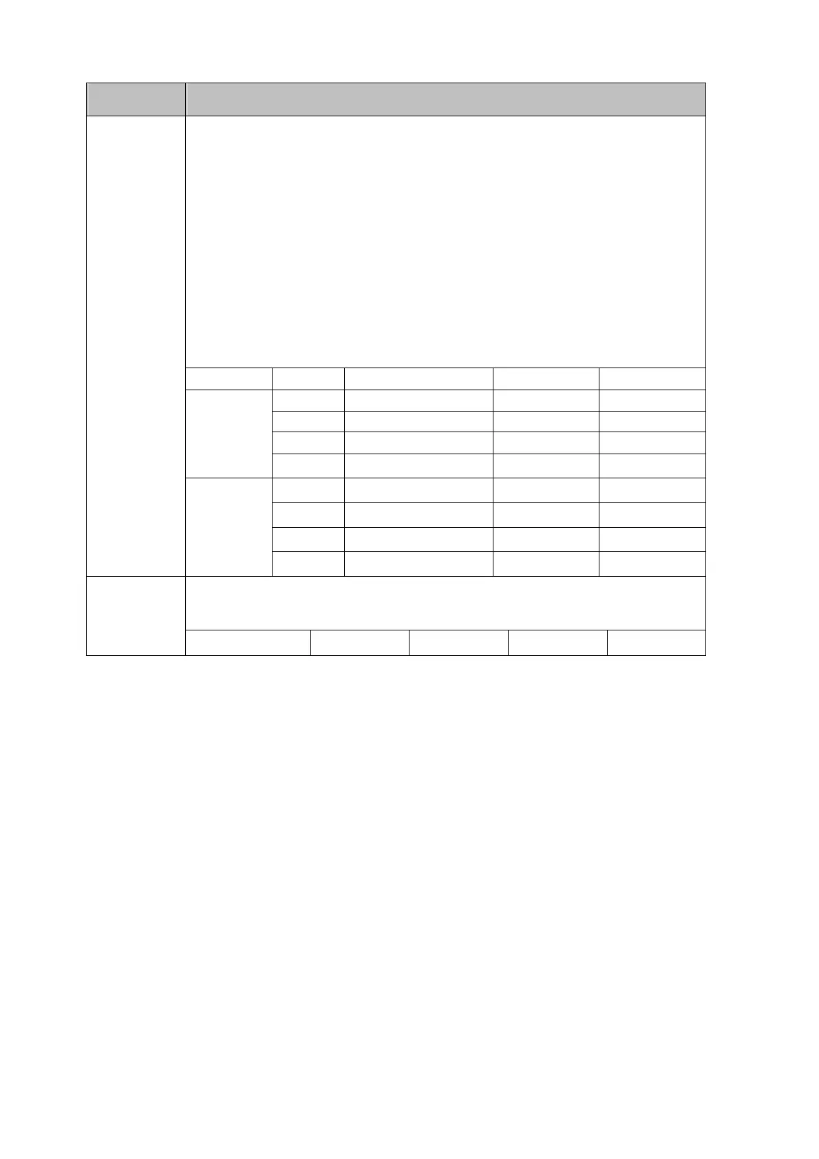
Table 6-9. Descriptions for R0 Command and Response (cont’d)
Response Description
<g
1
g
2
>
is a two-digit hex number; each digit contains 4-bit binary codes (Bit
7-4 and Bit 3-0) respectively to represent eight types of status about the
meter.
<g
1
>
indicates the status for four types of meter operation;
<g
2
>
indicates the ON/OFF status for other four types of meter operation,
Example: If
<h
1
h
2
> contains
a character string “18”, convert it to an 8-bit
binary code “00011000” that means the meter is under Auto-ranging for
Primary Display (1
st
Auto-Ranging) and the reading is on hold.
<g
1
g
2
>
Bit
Status
0 1
7 CAL Mode off on
6 Always 0
5 Shift Key off on
<g
1
>
4 Hold Reading off on
3 1
st
Auto-Ranging off on
2 2
nd
Auto-Ranging off on
1 MIN Recording off on
<g
1
g
2
>
<g
2
>
0 MAX Recording off on
<v>
is a single numeric numbers “0” to “3” used for representing the
intensity level of VFD display on the meter.
<v>
Intensity Level 0 1 2 3