61
Table 6-9. Descriptions for R0 Command and Response (cont’d)
<s
1
s
2
>
is a two-digit hex number; each digit contains 4-bit binary codes (Bit
7-4 and Bit 3-0) respectively to represent eight types of status about the
meter. For earlier than “v 1.20” which can be read by RV command, the
<s
1
s
2
>
is presented with 8-bit binary codes instead of two characters.
<s
1
>
indicates the status whether HI or LOW value for compare function is
under setting or not. The bits 7 and 6 are used to indicate AC or DC
dBm measurement, respectively. Both of bits 7 and 6 will be enabled
for AC+DC dBm measurement. There are available on “v 1.20” or later,
the version can be read by RV command.
<s
2
>
indicates the status for other functions of meter operation,
Example: If <s
1
s
2
> contains a character string “08”, convert it to an 8-bit
binary code “00001000” that means the meter is under TRIG mode.
<s
1
s
2
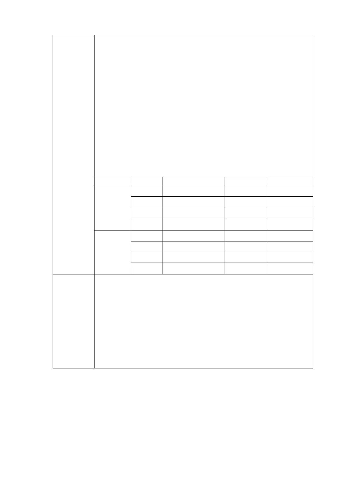
>
Bit
Status
0 1
7
AC
•
6
DC
•
5
Always 0
<s
1
>
4 HI/LO Setting Disable Enable
3 TRIG
Disable Enable
2 Buzzer off on
1 R_HOLD Data Hold Refresh Hold
<s
1
s
2
>
<s
2
>
0 % Disable Enable
<f
1
><r
1
>
and
<f
2
><r
2
>
<f
1
> indicates the measurement function in primary display. It contains
numeric value from “0” to “9” and character “A”.
<r
1
> is primary display measurement range The value is from “1” to “6”.
Please refer to Table 6-10 for an available value.
<f
2
> and <r
2
> are similar to <f
1
> and <r
1
> but representing the secondary
display status instead. If the meter is operated under single display
mode, <f
2
> and <r
2
> will not be returned.
For detail information of interpreting the < f
1
><r
1
> and <f
2
><r
2
>, please refer
to Table 6-11.