11
2.6 Definition of device interface
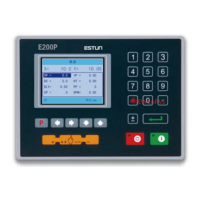
2.6.1 Definition of power interface
Definition of terminal is as shown in Table 2-2.
Table 2-2 Description of power terminal
Input terminal of device power, connect to DC +24V.
Input terminal of device power, connect to DC 0V.
2.6.2 Definition of input interface
Pin definition is as shown in Table 2-3.
Table 2-3 Definition of external output terminal
Step change signal, DC +24V signal input, connect to upper
dead point signal generally, beam return to upper dead
point, +24V signal is connected, system receive step change
signal, system callout the next program and execute the
program.
Back gauge retraction, signal, DC +24V signal input, avoid
interfering work piece by gauge device during work.
System X/Y axis positioning is finished, and slider gets away
from upper dead point. When slide just press against sheet,
retraction signal is connected. Back gauge will yield some
distance to direction of up counting (yield distance is
determined by program retraction value), avoid interference
by back gauge and work piece. When bending is finished
and slide return, back gauge will return from yield position.
X-axis reference point signal, DC +24V signal input, connect
to rear limit signal generally. When gauge touches reference
point switch, +24V signal is connected.