EasyManuals Logo

Estun E21 User Manual

Estun E21
41 pages
To Next Page IconTo Next Page
To Previous Page IconTo Previous Page
Page #13 background imageLoading...
Page #13 background image
E21 Installation Manual
10
2.5.4 Electrical wiring scheme
Electrical wiring scheme is as shown in Figure 2-4.
PG
12V single-point
incremental encoder
white 12V
black 0V
red PA
green
PB
yellow PC
Encoder cable
shield layer
shell
PG
12V single-point
incremental encoder
white 12V
black 0V
red PA
green
PB
yellow PC
shell
Y-ENCODER
2,7 5 4 3
1,6
8,9
X-ENCODER
2,7 5 4 3
1,6
8,9
Shell
grounding
Shell grounding terminal
POWER
24V 0V
24V switch
power
COM1
START
START
24V
COM2
24V
Encoder cable
shield layer
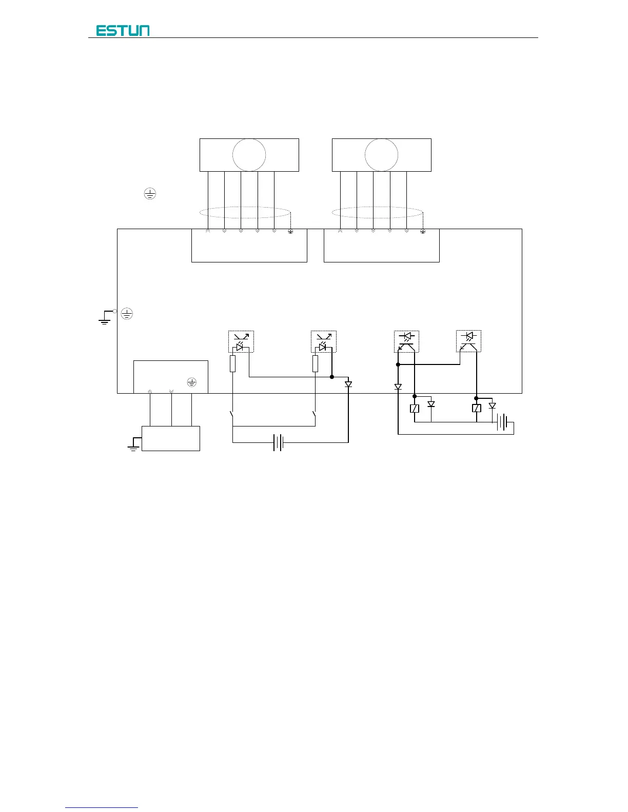
Figure 2-4 Electrical wiring schemes
It is recommended to use the relay which contains diode on coil, avoid high voltage
damage the circuit when cutting inductive load.
Shield layer of the encoder cable shall be connected to ground, which is the metal
housing of the product, with low resistor.

Table of Contents

Other manuals for Estun E21

Questions and Answers:

Question and Answer IconNeed help?

Do you have a question about the Estun E21 and is the answer not in the manual?

Estun E21 Specifications

General IconGeneral
BrandEstun
ModelE21
CategoryController
LanguageEnglish

Related product manuals