Do you have a question about the Estun E21 and is the answer not in the manual?
Manual guides operators for install, configure, maintain E21 device.
Installation & maintenance personnel can install & operate device.
Design complies with EMC and environmental test standards.
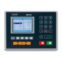
Details LCD display dimensions, dot matrix, and status light colors.
Capable of storing 40 programs, each with 25 steps.
Lists input/output voltage, current, and encoder power specs.
Safety precautions before starting installation and wiring.
Recommended space and direction for device installation.
Conditions to avoid for optimal installation and operation.
Details panel mounting dimensions and installation diagram.
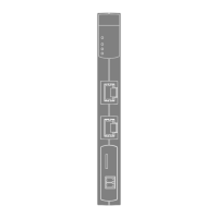
Diagram showing rear panel layout, including ports.
Details socket numbers, names, and descriptions for rear panel ports.
Defines various device interfaces like power, input, output, encoder, and communication.
Steps to access and navigate the parameter setting pages.
Details of various parameters for machine tool configuration.
Description of parameters related to motor speed detection settings.
Steps to access the diagnostic menu for system testing.
Procedure to test system input signals and port status.
Procedure to test system output signals and relay operations.
Procedure to test keyboard input and display corresponding key names.
Procedure to diagnose the FRAM (memory) for OK or failure status.
Procedure to test encoder functionality by monitoring C-pulse changes.
Procedure to diagnose the LCD display functionality.
Procedure to test communication between two connected devices.
Checks and preparations required before starting the commissioning process.
Detailed steps for system parameter setting and commissioning.
Procedure for verifying motor movement direction and encoder counting.
Procedure for fine-tuning axis positioning accuracy.
Procedure for verifying the counting function during operation.
Procedure for verifying the retreat function and sequence.
Procedure for adjusting axis positions and scale errors using teach function.
General safety and operational instructions for performing maintenance.
Schedule and items for regular inspection of the system.
Items for inspection every 6 months or 1 year.
Description and recommendations for external power supply connections.
Details on internal circuit and chassis grounding for safety and performance.
Measures to ensure electromagnetic compatibility and protect the system.
Demonstration of wiring for AC asynchronous motors.
| Model | E21 |
|---|---|
| Input Voltage | 220V AC |
| Output Voltage | 24V DC |
| Display | LCD |
| Axes | 2 |
| Backgauge control | Yes |
| Protection Level | IP20 |
| Type | Controller |
| Communication Interface | RS232 |
| Operating Temperature | 0°C to 45°C |
| Storage Temperature | -20°C to 60°C |
| Humidity | 20% to 80% (non-condensing) |