Do you have a question about the Estun E-Series and is the answer not in the manual?
Provides guides to use the E300 device for the jobs.
Specifies the intended users of the document, including engineers and operating staff.
Outlines the document structure, consisting of three chapters.
Defines symbols and general conventions used throughout the manual.
Defines symbols for WARNING, CAUTION, MANDATORY, PROHIBITED, and INFO.
Explains text formatting for paragraphs, filenames, terminal display, and book titles.
Details formatting for buttons, menus, and dialog titles in the graphical user interface.
Describes how to interpret key presses and key combinations.
Introduces the E300 as an NC device for Torsion Bending Machines.
Lists key features of the E300 device, including 4-axis support and flexible IO allocation.
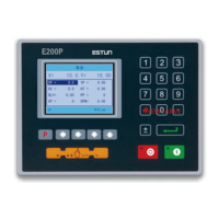
Describes the physical appearance of the suspended device and its control panel elements.
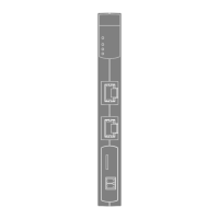
Details the types and descriptions of the six ports available on the E300 device.
Provides detailed electrical specifications for power supply, inputs, outputs, and encoder.
Outlines communication protocols, transmission rates, and ESD protection.
Specifies parameters for analog input, including range, resolution, and channels.
Specifies parameters for analog output, including range, resolution, and channels.
Lists operating and storage temperature and humidity requirements for the device.
Explains the layout of the initial page: Title Bar, Axis Position, Parameters, and Navigation Bar.
Describes system statuses like Not Ready, Idle, Run, and Alarm.
Details the different operation modes: Single, JOG, and Continue.
Area displaying the current position value of the machine's axes.
Area displaying parameter information for each page.
Area displaying parameter details, including editing value and range.
Shows accessible main pages via F1-F6 keys.
Presents a flow diagram of operations and key presses.
Explains programming for quick bending and the initial Single-Step page.
Explains multi-step programming for complex bending and accessing the Multi-Step page.
Details how to manually move servo axes using arrow keys in the Manual page.
Explains setting die parameters on the Die page.
Covers angle and axis corrections for accurate bending results.
Corrects Y-axis position when actual and displayed values differ.
Corrects X-axis position when actual and displayed values differ.
Covers creating, editing, and deleting programs.
Explains how to create a new program by entering a name.
Details how to edit an existing program by selecting its ID.
Describes how to delete a program by selecting its ID.
Explains the Teaching operation for obtaining servo axis positions.
Describes teaching Y-axis and setting clamping point for accurate positioning.
Details measuring and teaching X-axis position for processing accuracy.
Explains measuring and teaching R-axis position directly.
Explains how to start the machine using the START key.
Describes the indicator lamp and status display (RUN) when the device is running.
Details the three cases for stopping the device: fault, manual, and emergency.
Describes the indicator lamp and status display (Idle or Alarm) when the device is stopped.
Explains alarm information, causes, and how to reset alarms.
Describes viewing ports, valve status, and fault lists on the Status Monitor page.
Details how to view output status of valves on the Valve Status tab.
Explains viewing input/output status on the IO Status table.
Describes viewing the Alarm Record table for past alarms.
Covers commonly used parameters like language, unit, count mode, and system time.
| Series | E-Series |
|---|---|
| Category | Controller |
| Control Modes | Position, Speed, Torque |
| Protection Level | IP20 |
| Feedback | Incremental encoder, Absolute encoder |
| Operating Temperature | 0°C to 45°C |