ESTUN AUTOMATION Proprietary
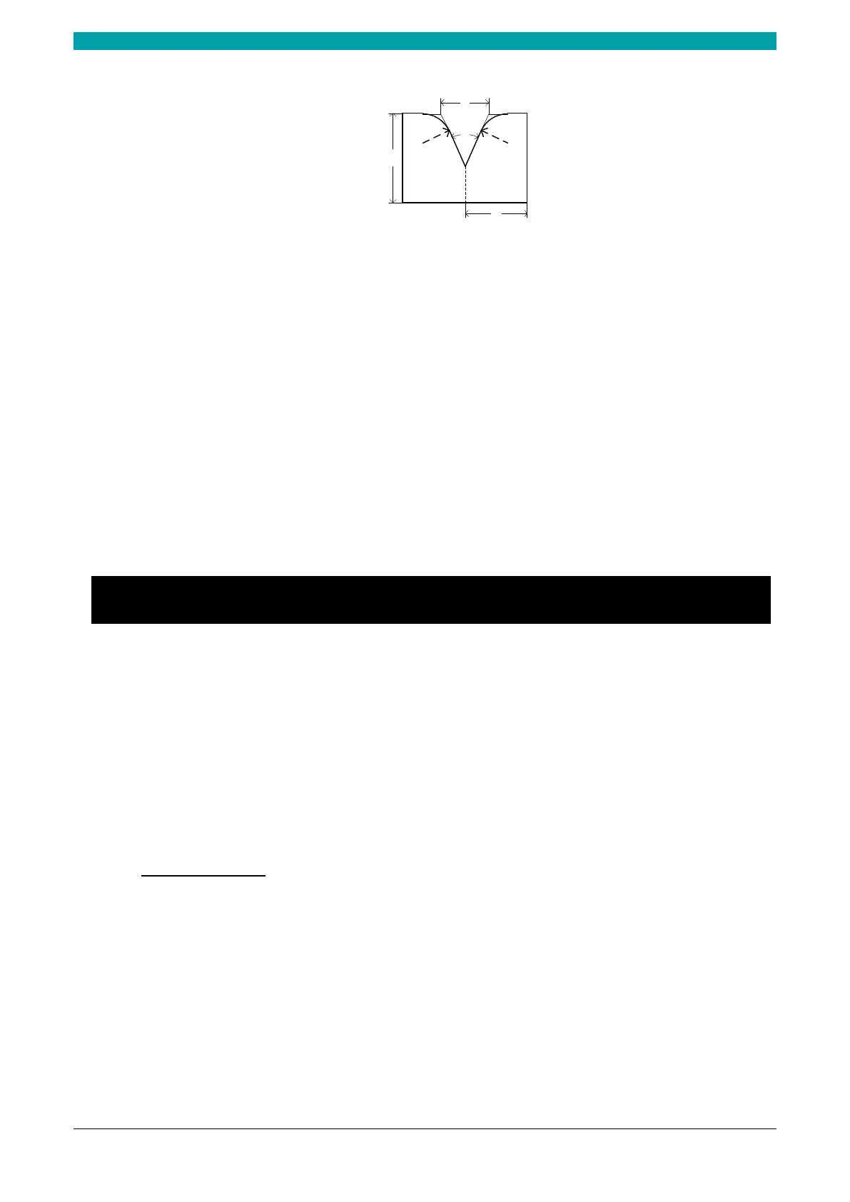
Figure 2-7 The technical parameters diagram of the die
H: The height of the die, which is used in the bend depth calculation.
V: The length of V-opening, which is the distance between the touching lines crossing.
α: The angle of the die.
R: The radius of the edges of the V-opening.
S: Safety distance, which will be used in the case an R-axis, is mounted. This to prevent finger to
die collision. The indicated minimum value is computed automatically from the die dimensions
as follows:
S = FS + V/2, in which:
FS = flat section on the back side of the V-grove
V = opening value.
2.7 Bend Correction
It is necessary to commission the machine before your actual processing, in order to win an accurate
bending result.
For performing it, you can program a bending process on Single-Step page, and operate the machine
to complete one processing.
Then, measure the actual bending angle, bending depth, and the distance of the back gauge.
Check whether the bending result is corresponding with your requirement.
Angle correction
The range of this parameter is from -90 to 90.
When the actual axis position is not corresponding with the displayed value, it is possible to correct
the position with this parameter.
For example:
When the programmed and displayed value is 90, while the actual axis position value is 92, then
you shall set the Corr.
to -2.
When the programmed and displayed value is 90, while the actual axis position value is 88, then
you shall set the Corr.
to 2.
 Loading...