26
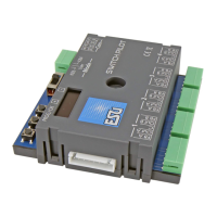
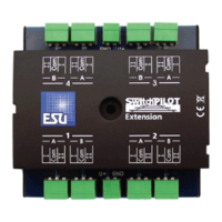
15.2. Technical data SwitchPilot Extension
Operating modes:
• Extension module for SwitchPilot, power is supplied by the latter.
Relay outputs are controlled by SwitchPilot.
Outputs:
• 4 Relays with two outputs each (2 x changers), switched as one,
with screw terminals for potential-free switching or power supply
for electro-frogs.
• Maximum load per relay output: 30V AC, 2 A continuous.
Dimensions in mm:
• app. 86mm x 86mm x 25mm
Technical data
15. Technical data
15.1. Technical data SwitchPilot V2.0
Operating modes:
• NMRA/DCC „Accessory Decoder“ compatible. Address range
from 1 - 2044
• Märklin® Motorola®compatible, up to turnout number 384. k83
compatible. k84 logic
• Power supply by digital command station or separate DC-power
supply.
• Maximum supply voltage: 18V AC or 24V smooth DC.
• Transistor outputs 1 to 4:
• 4 outputs with two transistors each, each with 1.5A continuous,
2.0A peak (20 seconds).
• Total maximum load of device: 2.0A continuous, 3.0A peak (20
seconds)
• Overload and short circuit protection for outputs.
• Switching time of each output between 0.06 sec to 2.00 sec or
adjustable for variable. Optional blinking mode and „zoom“-effect
for lighting effects.
• Servo outputs:
• 2 Servo outputs for RC-servos (e.g.: Graupner® JR, Futaba® or
ESU), adjustable pulse duration between 1.0 msec and 2.0 msec,
positive pulse. Adjustable speed and end positions.
• Power supply for the servos with 5V stabilised supply. Maximum
current draw oft he servo: 250 mA continuous, 500 mA peak (20
seconds)
• Feed back:
• ntegral RailCom® status feedback reports turnout status via the
tracks and can be displayed on ECoS (amongst others).
• Dimensions in mm:
• app. 86mm x 86mm x 25mm
 Loading...