6
The SwitchPilot Familie
The operating mode switch is only for the use with Motorola con-
trol units to enable compatibility with Marklin controllers. If the
SwitchPilot is used with the DCC protocol the operating mode
switch needs to stay at the middle position (factory default).
5.2.1.1. k83 mode
When you push the slide into the k83 position then the outputs
1 to 4 will be switched to pulse operation regardless of the pro-
gramed settings. The SwitchPilot behaves exactly like a Märklin®
k83. Use this mode whenever you want to operate conventional
solenoid drives.
5.2.1.2. k84 mode
In the k84-mode the outputs 1 to 4 will be set to variable re-
gardless of any pre-programed settings. The SwitchPilot behaves
exactly like a Märklin® k84. Use this mode to operate LEDs or light
bulbs and whenever you do not require any specific programming.
All consumer loads are directly electrified by the SwitchPilot. You
must not connect any external voltage!
5.2.1.3.User mode
The user mode is switched on by setting the switch for selecting
the operating mode into the centre position. Only in this mode the
outputs 1 to 4 will behave according to the software controlled
settings. This is the correct use to DCC format, k83 and k84-Mo-
dus are only meant for Motorola® command stations.
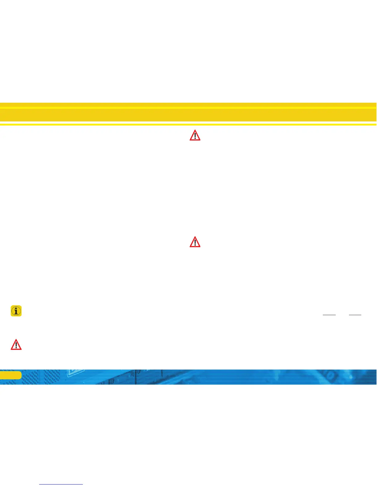
5.2.2. Transistor outputs
The SwitchPilot has a total of 8 transistor outputs that are grouped
in four pairs 1 to 4. Each pair has two outputs, OutA and OutB.
there are also two separate servo outputs.
The transistor outputs can be set to continuous, to pulsed power
or to alternating blinking.
If requested, the pulse signal can be disabled when the end po-
sition of the lever is reached. Furthermore, the power supply to
each servo can be interrupted to prevent any “twitching” of some
cheaper servos. Due to the integral DCC RailCom® - transmitter
it is possible to provide status feed back of the accessory to the
command station. For instance an ESU ECoS command station can
then display the manually activated change of status.
Of course the transistor outputs of SwitchPilot are electronically
protected against overload and short circuit.
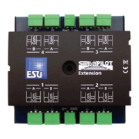
5.1.3. SwitchPilot Extension
For operating motor drives for turnouts or for the polarization of
the frogs you require a relay with potential free contacts. For this
purpose each SwitchPilot can be connected to a SwitchPilot Ex-
tension which can be plugged into the side of the SwitchPilot and
receive its power from it.
Each SwitchPilot Extension module has 4 by 2 relay outputs that
are operated in parallel to the corresponding outputs of the
SwitchPilot. This corresponds to the established k84-solution.
5.2. Features
5.2.1. Operational modes
All SwitchPilots are multi protocol capable and therefore can
either be operated with command stations as per the Märklin®-
Motorola® system (e.g.: 6021, Central Station®) or with DCC
compliant command stations. For this SwitchPilot decoders must
be contacted with solenoid accessory addresses.
Therefore, operation with the Lokmaus 2 is not possible. The Lok-
maus 2 does not send DCC commands to solenoid devices.
The SwitchPilot has a switch to select different operating modes.
Thus you can easily set the desired mode. Therefore “program-
ming” is not necessary for most standard applications.
This switch only operates the four transistor output pairs 1 to 4.
The servo outputs are not affected.