5
4. How this manual will help you
This manual was divided into a few chapters, which will gradually
show you how to operate the SwitchPilot products.
Chapter 5 includes an overview of the features of the single
SwitchPilot decoders.
In chapter 6 we deal with the connection of your layout.
If you wish to adjust the factory settings of your decoder individu-
ally, just do so. In chapter 7 - 11, you will find detailed explanations
about which settings are possible and how you can change them.
Statements about technical data can be found in chapter 15 as
well as a list of all CVs assisted, if necessary.
By using the LokProgrammer, a new firmware file can be downloa-
ded to the SwitchPilot any time.
5. Introduction – The SwitchPilot family
5.1. Members of the SwitchPilot family
The ESU SwitchPilot decoders are especially optimized for statio-
nary operation on your layout. Not matter if you wish to activate
turnouts, signals, magnetic un-couplers, light bulbs and other
stationary loads or even if you prefer a „state of the art servo
motor: One of the SwitchPilot decoders will be quite useful for
you, for sure.
The SwitchPilot decoders can be supplied with power either from
the digital system or from an external DC-power source. Due to an
installed full bridge rectification and backup memory you can do
without any additional „power modules“.
All SwitchPilots are multi protocol capable and therefore can
either be operated with command stations as per the Märklin®-
Motorola® system (e.g.: 6021, Central Station®) or with DCC
compliant command stations.
SwitchPilot Decoders are able to control all current DCC program-
ming modes and can be set up either on the main track or the
programming track. Thanks to RailCom® it is also possible to read
out data on the main track. Some of the SwitchPilot decoders can
be easily set up via a three-button, LED input unit.
By using the LokProgrammer, a new firmware file can be downloa-
ded to the SwitchPilot any time.
SwitchPilot decoders are shipped in a robust body and stand out
due to their excellent price-performance ratio.
5.1.1. SwitchPilot overview
SwitchPilot V2.0 SwitchPilot Servo V2.0
DCC mode
Ok
Motorola mode
Ok Ok
DCC programming
Ok Ok
4 double transistor outputs
je 1,5A -
LED Monitor for outputs Ok -
2 servo outputs
Ok -
4 servo outputs
- Ok
Feedback input
Ok -
RailCom®
Ok Ok
Input unit
- Ok
Updatable Ok Ok
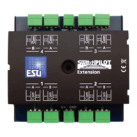
5.1.2. SwitchPilot V2.0
The SwitchPilot is a universal decoder for users who mainly have
double-solenoid motors installed, but would like to test the ser-
vo technology. Hence the SwitchPilot has four outputs (1-4) for
switching of up to 4 double-solenoid accessories (e.g. switches) or
8 accessories like uncouplers or light functions. Each output can
be programed individually for continuous or pulsed output with
variable pulse duration or blinking. Thus it is possible to connect
light bulbs or LEDs without any additional relays. Automatic fading
assures prototypical run-up and shut-down of signal lamps.
In addition two commercially available RC-servos for hobby appli-
cations may be wired directly to the SwitchPilot (outputs 5 – 6).
Their speed and end position can be adapted as required.