13 | Hardware Description
ETAS ES582.2 | User Guide
Timestamp
The ES582.2 assigns a timestamp to the CAN messages. The measured data
acquired by the ES582.2 module is synchronized by the INCA application software
with signals of other ECUs and measuring modules at high speed.
Feature
The CAN applications supported by the ES582.2 are located in an overview in chap-
ter 5.9.2 on
page
30.
Bus terminating resistor
The CAN interface requires the use of bus terminating resistors in both operating
modes. According to the CAN specification, one bus terminating resistor each of
120 ohm is required at the two open ends of the bus. It must be connected to the
cable or the plug. ETAS offers cables and terminating resistors of 120 ohm to set up
CAN networks.
Some CAN networks are already terminated (e.g. inside a vehicle), so that no addi-
tional termination is required.
Minimum requirements for the CAN connections
At least the following connections are required for a connection to the CAN net-
work:
- Pin 2 CAN Low
- Pin 7 CAN High
- Pin 6 or Pin 3 GND (one of the pins can optionally be connected)
The ground connection (GND) must be identical with the ground connection of the
other CAN nodes on the bus.
Y-cable
A Y-cable (CBCF100, see also 6.1 on page 34) allows access of both CAN interfaces
to the CAN bus.
2.4.2 USB Port
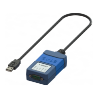
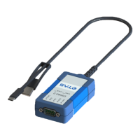
The module can be connected to a PC or drive recorder via a permanently con-
nected cable with a USB combo plug.
NOTE
The module must be operated directly on the USB connection of a PC, a drive
recorder or an active hub whose USB interface meets the requirements listed in
the table in chapter 5.9.1 on
page 29.
The use of USB cables for extending the connection between ES582.2 and PC or
drive recorder is not allowed.


 To Next Page