1 Installation and User Interface Overview 10
Single Processor System
LightDesigner configurations with only a single processor will automatically resolve
processor number (identity) and IP settings when loaded onto a processor. No additional
setup is required.
Step 1: Use removable media to load the LightDesigner configuration file. See “Load
Architectural Configuration” on page 61. Alternatively you may load the
configuration file from a PC through the Ethernet port on the front of the
Paradigm ACP.
Multiple Processor System
Multiple processor systems require that you set each processor’s unique number (identity)
before loading a LightDesigner configuration file.
Step 1: Set the processor number (identity) from the “Select New Settings” menu list
located in Assign Processor/IP menu. This action also selects processor IP
settings. Reference “Assign Processor / IP”, page 44.
Step 2: Repeat “Step 1:”, for all processors in the Paradigm system utilizing a unique
processor number for each.
Step 3: Load the architectural configuration into all online processors in the system. Use
either a removable media device, upload from LightDesigner when connected to
Ethernet, or request it from another online processor. See “Load Architectural
Configuration” on page 61.
System Status
When the Paradigm ACP is installed properly and power is applied to the enclosure, the
graphic LCD illuminates and displays system status.
When the Paradigm ACP is installed in a host DRd rack, the default status displays
Dimming Rack Status.
When the Paradigm ACP is installed in a host ERn enclosure, only the Arch Control Status
is displayed. Check the status LEDs for indication of power, control, and rack status.
• The “Power” LED illuminates blue when power is applied to the Paradigm ACP.
• The “DMX A” LED illuminates solid green to indicate when a DMX signal is present.
When the DMX input signal has an error or is not present, the LED will flash.
• The “DMX B” LED illuminates solid green to indicate when a DMX signal is present.
When the DMX input signal has an error or is not present, the LED will flash.
• The “Ethernet” LED flickers green to indicate network activity or traffic, and remains off
when Ethernet is not connected.
• The “Error” LED flashes red when any system errors or warnings exist. This error LED
is accompanied by status messages on the LCD. See “View/Clear Errors Menu” on
page 65.
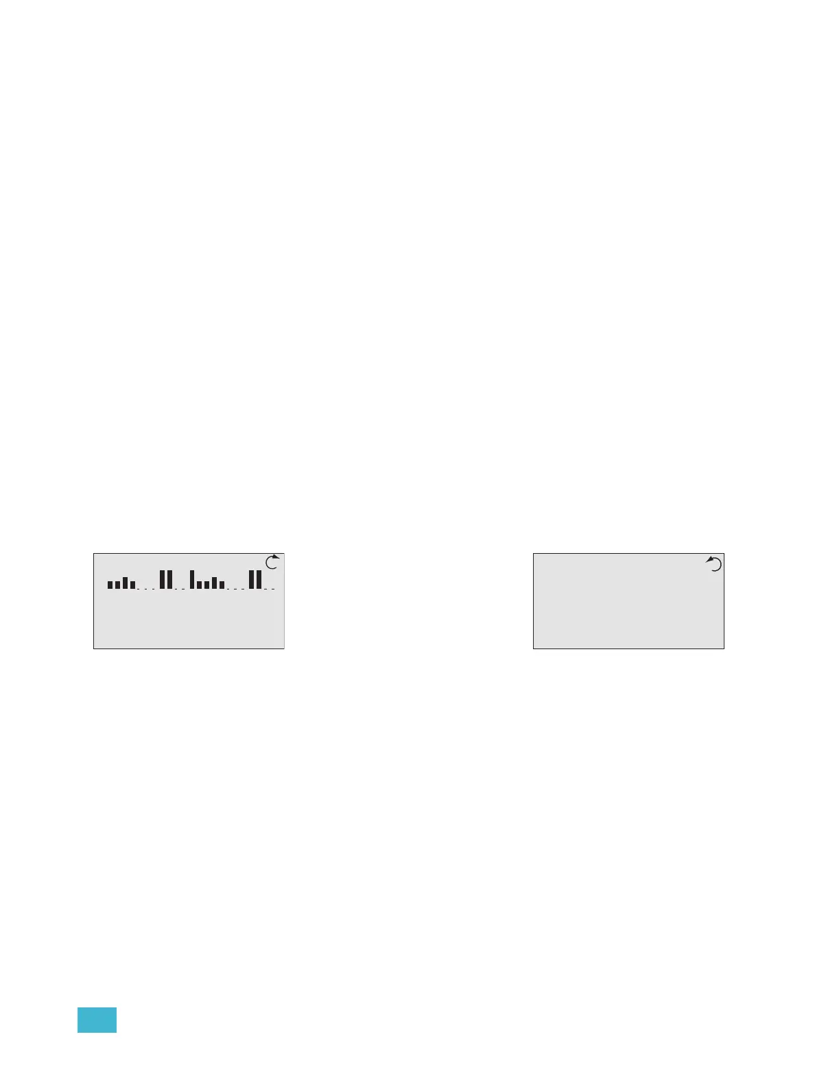
Dimming Rack Status
System OK
DMX Start = 1
Ø1: 119 Ø2: 119 Ø3: 120
60Hz 102F v1.0.2
Arch Control Status
Processor Name
IP: 10.101.10.101
System OK
DMX A: In Inactive
DMX B: Out Active
DRd12 v1.4.5
• Clockwise rotation on the touch
wheel changes the status display
to Arch Control Status.
• Counter-clockwise rotation on the
touch wheel changes the status
display back to Dimming Rack
Status.