17 Paradigm Architectural Control Processor Configuration Manual
Status Display
The Paradigm architectural control processor (P-ACP) provides all of the basic rack and
system information on the status display. When the Paradigm ACP is installed in a DRd
enclosure, the dimming rack status display is the default status display. The architectural
control status display is the only status display available when the Paradigm ACP is
installed in an ERn enclosure.
DRd Dimming Rack Status Display
• display title - A menu’s title appears in the first row of every display for easy navigation.
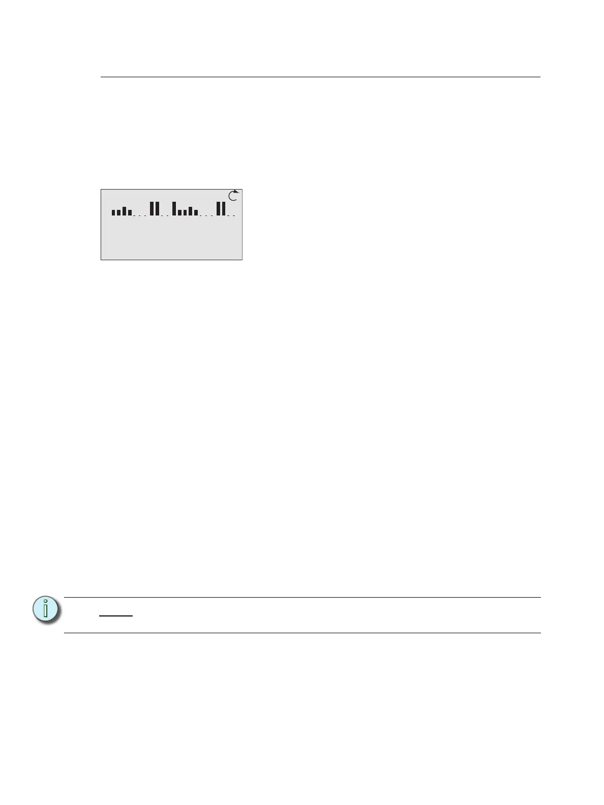
• scroll to next display - When the clockwise symbol appears in the display, use the
touch wheel to scroll clockwise to the Arch Control Status display. When the counter-
clockwise symbol appears, use the touch wheel to scroll counter-clockwise for the
previous display.
• rack dimmer levels - A DRd enclosure with 1 to 24 channels will display all dimmers
with proportional levels on the line beneath the display title (as pictured above). Cross-
bussed DRd enclosure display dimmers 1-24 on the top line beneath the display title
and dimmers 25-48 on the next line.
• status message area - Status messages are common to both the Dimming Rack
Status and Arch Control Status displays. When a system error is detected, the
message changes to reflect the specific error type. When multiple errors are detected,
each error message cycles, in increasing numerical order (i.e. Dimmer 1 error, Dimmer
2 error, etc.) on the display for 1 second each. Reference “Status / Error Messages” on
page 19 for a complete listing of possible errors and the actions required to clear them.
• DMX start address - Indicates the DMX start address of the first circuit in the DRd
enclosure. An equal sign (=) before the address number indicates a 1 to 1 patch of DMX
address to the dimmers in the rack. An approximate equal sign
≈ before the address
number indicates advanced patching. Reference the “Dimming Setup Menu” on page
30 for details on patching.
• per phase voltage - Each phase of power is measured and represented on the
Dimming Rack status display. When the rack is configured for bi-phase, only phases 1
and 2 are shown, when the rack is configured for single phase, only the single phase
data is available.
• operating frequency - The operating frequency is measured and represented on the
dimming rack status display.
Note:
Voltage displayed is a user convenience and is approximate. It is not as accurate
as using proper voltage measurement equipment.
Dimming Rack Status
System OK
DMX Start = 1
Ø1: 119 Ø2: 119 Ø3: 120
60Hz 102F v1.0.2