15
27330-01A
Installation - Remote Connections
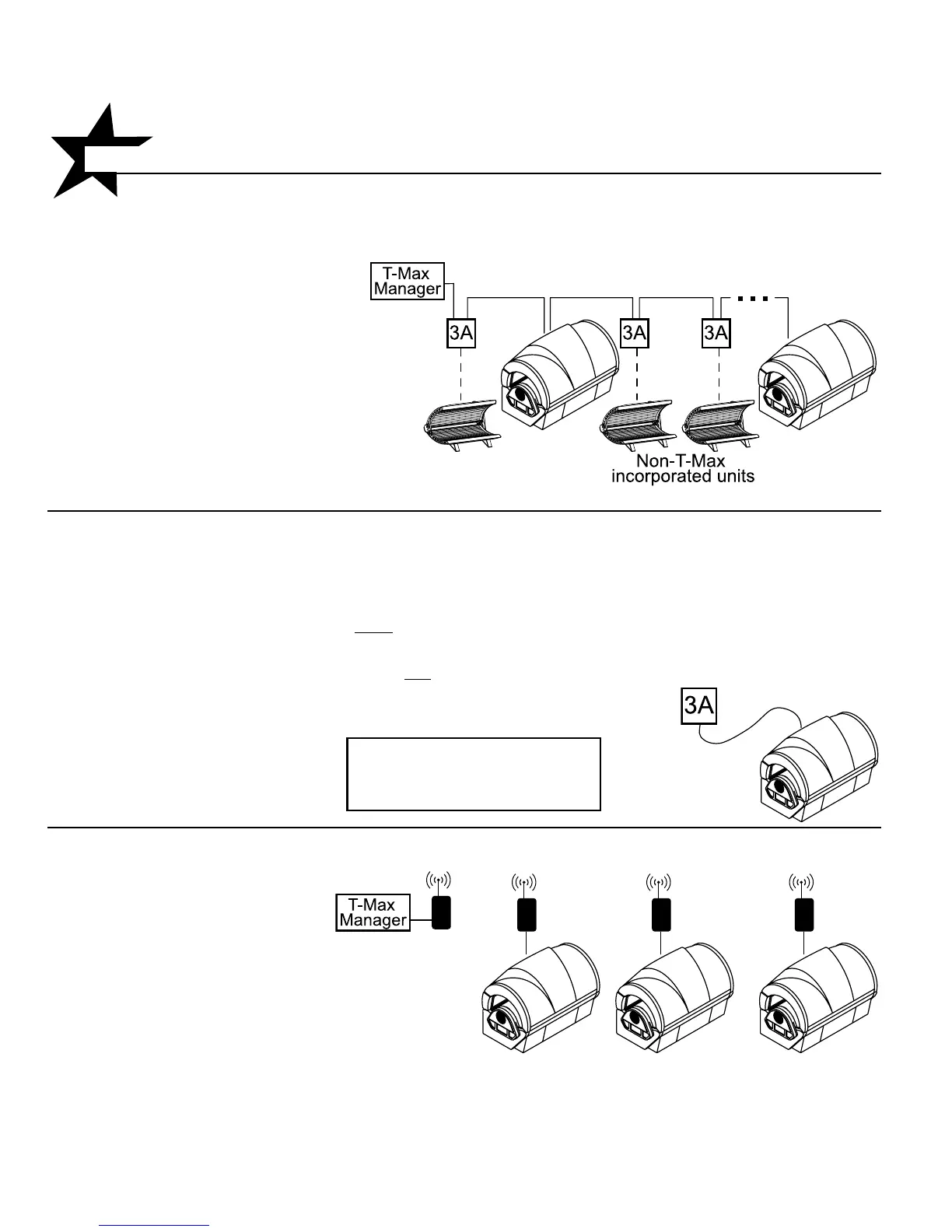
Scenario 1 - T-Max® Manager Series with wires
This system is ideal for multiple sunbed installa-
tions. Simply connect the RJ-22 modu-
lar cable(s), described in the T-Max®
Manager manual, into the remote
port(s) located on the ballast drawer and follow
the instructions that came with your remote
system. If you have an older T-Max® Manager
that does not support auto addressing, set
the address of each sunbed manually as
described in Setting the address manually.
You can place your sunbed at any location in
the series.
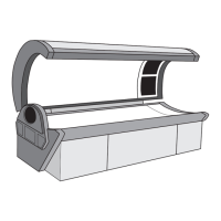
Scenario 2 - Single Bed wired to T-Max® 3A
In single sunbed installations, the T-Max® 1A and
3A can offer the same control as the T-Max®
Manager, eliminating the need for a Manager. If
you’re using a 1A in this manner, it must
have a
chip labelled “master” installed on its circuit
board. The remote control bypass plug must not
be
used in this configuration. The 3A may be used as
a “master” with no modification.
NOTE: A T-Max® 1A with a
“master” chip can be substituted
for a 3A.
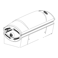
Scenario 3 - T-Max® Manager
Series with Complete Wireless
Connect one AP-900 Retail to the
Manager and one AP-900 OEM
to each of the tanning beds.
Install as many beds as you like
with this configuration. Units that
do not communicate with T-Max
will need an AP-900 Retail and
an additional 3A to operate.
After you have set the T-Max® 1A’s, or 3A’s, address
to “0” (refer to your T-Max® user’s guide) and the
sunbed’s address to “1”, simply connect the RJ-22
modular cables, described in the T-Max® user’s
guide, directly into either of the smaller ports locat-
ed on the ballast drawer and either port on the
back of the T-Max® 1A
or 3A.