13
2096580-16-11/22 (translation of the original operating instructions)
Operating Instructions
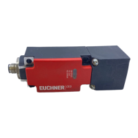
Non-Contact Safety Switch CES-A-.5
EN
9.4. Connector assignment of safety switch CES-A-.5
1 0 V 5 OUT
2 + UB 6 +LA
3 LA 7 -LAB
4 LB 8 +LB
View of connection side of the device
The shield on the connecting cable is connected inter-
nally to the device’s shield spring via the knurled nut
on the M12 plug connector.
8
3
5
7
4
21
6
Fig. 1: Connector assignment of safety switch CES-A-.5
9.5. Correct connection
WARNING
In the event of a fault, loss of the safety function due to incorrect connection.
Ì To ensure safety, both safety outputs (LA and LB) must always be evaluated.
Ì To achieve category 3/4 according to EN ISO 13849-1, it is necessary to monitor the downstream
contactors.
M
+ 24 V
+ 24 V
+ 24 V
0 V
+U
B
OUT
-LAB
LB
+LB
LA
+LA
Monitoring output
(no safety fnction!)
Safety output LB
Safety outpu LA
To the
control system
Application
CES-A-C5...