Operating Instructions
Non-Contact Safety Switch CES-A-.5
8
(translation of the original operating instructions) 2096580-16-11/22
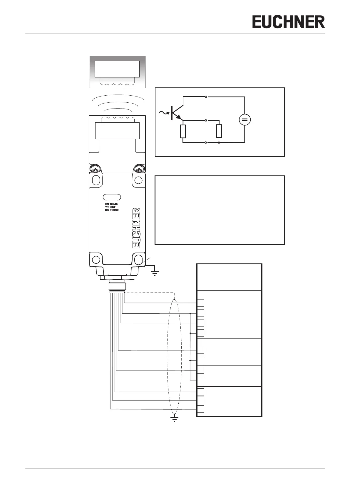
6.3. Block diagram
1
2
3
4
5
6
7
8
0V
+ U
LA
LB
OUT
+LA
-LAB
+LB
B
I1
O1
0 V
0 V
E2
I9
O9
0 V
0V
0 V
OUT
DC +24 V
+LB
-LAB
LB
+LA
LA
+ U
0V
(RD)
(BU)
(YE)
(PK)
(GN)
(GY)
(BN)
(WH)
+LA
LA
R
B
-LAB
+
-
Trans-
ponder
Pin assignment:
Common ground for output A and B
Load A
Pin
Core color
WH/white
BN/brown
GN/green
YE/yellow
GY/gray
PK/pink
BU/blue
RD/red
Function
Coded
actuator
Read head with
evaluation unit
CES-A-.5
Housing:
118 x 40 x 40 mm
Connection:
M 12x1
8-pin, screened
Read head
Safety input
Pulsed output
Input
Safety input
Pulsed output
Output circuit:
Screen bonding clamp
The screen on the connection cable
is connected internally to the screen
bonding clamp on the housing.
Safety PLC
with static /
dynamic signals
Connection example with
safety PLC PSS 3056 (PILZ)
Power
supply
for load A
Test pulse 0
Test pulse 1