Operating Instructions
Transponder-Coded Safety Switch CET.-AS-…
18
(Translation of the original operating instructions) 2113689-04-07/19
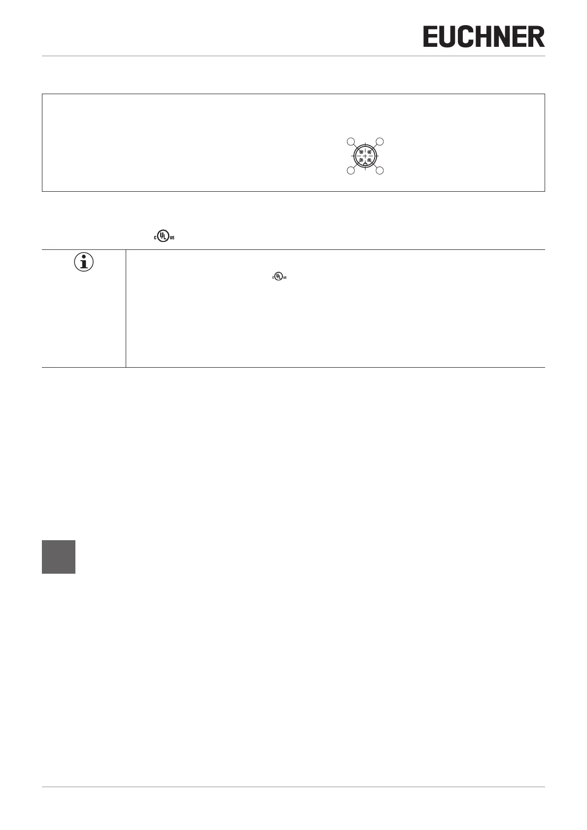
10. Electrical connection
1 AS-Interface +
2 Auxiliary voltage 0 V
3 AS-Interface -
4 Auxiliary voltage 24 V
View of safety switch
plug connector
Figure 3: Terminal assignment, AS-Interface M12 plug connector
10.1. Notes about
Important!
Ì For use and operation as per the requirements
1)
, a power supply with the feature “for use in
class 2 circuits” must be used.
Alternative solutions must comply with the following requirements:
Electrically isolated power supply unit in combination with fuse as per UL248. This fuse should be
designed for max. 3.3A and should be integrated into the 30 V DC voltage section.
1) Note on the scope of the UL approval: the devices have been tested as per the requirements of UL508 and CSA/ C22.2 no. 14 (protection against electric shock
and re).
10.2. Setting the AS-Interface address
The address can be set prior to or after mounting.
The AS-Interface address of the safety switch is set using an AS-Interface programming device. Addresses 1 to 31 are valid.
The unit is programmed by connecting the programming device to the M12 plug connector of the safety switch with a
programming cable.
Address 0 is the default setting on delivery (the AS-Interface LED ashes alternately red/yellow).
10.3. Conguration in the AS-Interface safety monitor
(see operating instructions for the AS-Interface safety monitor)
10.3.1. Dual-channel dependent
The safety switch is congured in the AS-Interface safety monitor with the AS-Interface address set as follows,
for example:
Ì Dual-channel dependent
Ì With or without start-up test
Ì Synchronization time = innite
In this operating mode, the guard must be opened each time prior to restarting.
Cat.
4

 Loading...


