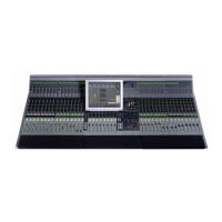
Euphonix Max Air Installation Guide
17
Chapter 2: Interconnecting System
Components
This chapter summarizes technical information for Max Air’s components, including size,
weight, power consumption, cooling, and fuse requirements and shows their interconnections.
To plan an installation, examine Figure 2-1 to learn about suggested equipment locations.
The Sync, MADI, and Control hookup diagrams (Figure 2-7 through Figure 2-10) all show
maximum cable distances.

 Loading...