Euphonix Max Air Installation Guide Max Air Components
33
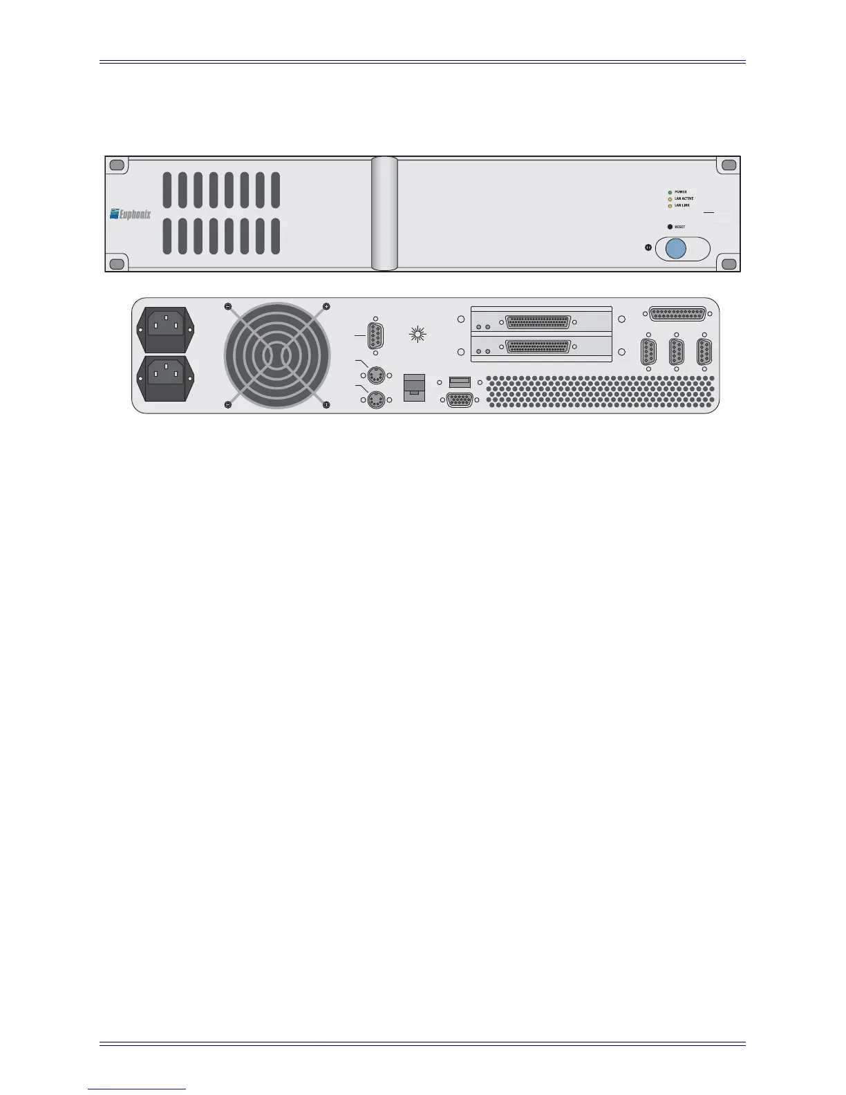
PC253i Interface Computer
Figure 3-7 PC253i Front and Rear Panels
Parallel Port (DB-25): Connect to MOTU MIDI I/F via DB-25 (provided).
TCC Main Port (Lower DB-62): Connect TCC breakout cable (provided) to this port. This
cable breaks out to four DB-15 connectors that provide control hookup for the MC524
Monitor Interface and three ML530 Mic/Line Interfaces.
TCC Extension Port (Upper DB-62): Connect a second TCC breakout cable (provided) to
this port to connect up to four additional ML530 Mic/Line Interfaces.
Network Port (RJ45): Connect to the EuCon Network Switch via the RJ45 cable (provided).
Parallel Port (DB-25): Connect to MIDI Interface.
Serial Port 1 (DB-9):Connect to control port on SH612 (optional).
Power Connectors (IEC): Accepts two standard IEC power cords (provided). Two autorang-
ing switching supplies accept voltages between 100–240 VAC, 50–60 Hz.
INTERFACE PILOT COMPUTER
P
2
PILOT ID
1
2
3
4
5
6
7
8
9
10
11
12
13
14
15
16
MOUSE
KEYBOARD
PS/2
LAN
USB
PARALLEL
SERIAL 1
SERIAL 2
VGA
POWER
STATUS

 Loading...


