Euphonix Max Air Installation Guide Max Air Components
30
Max Air Console
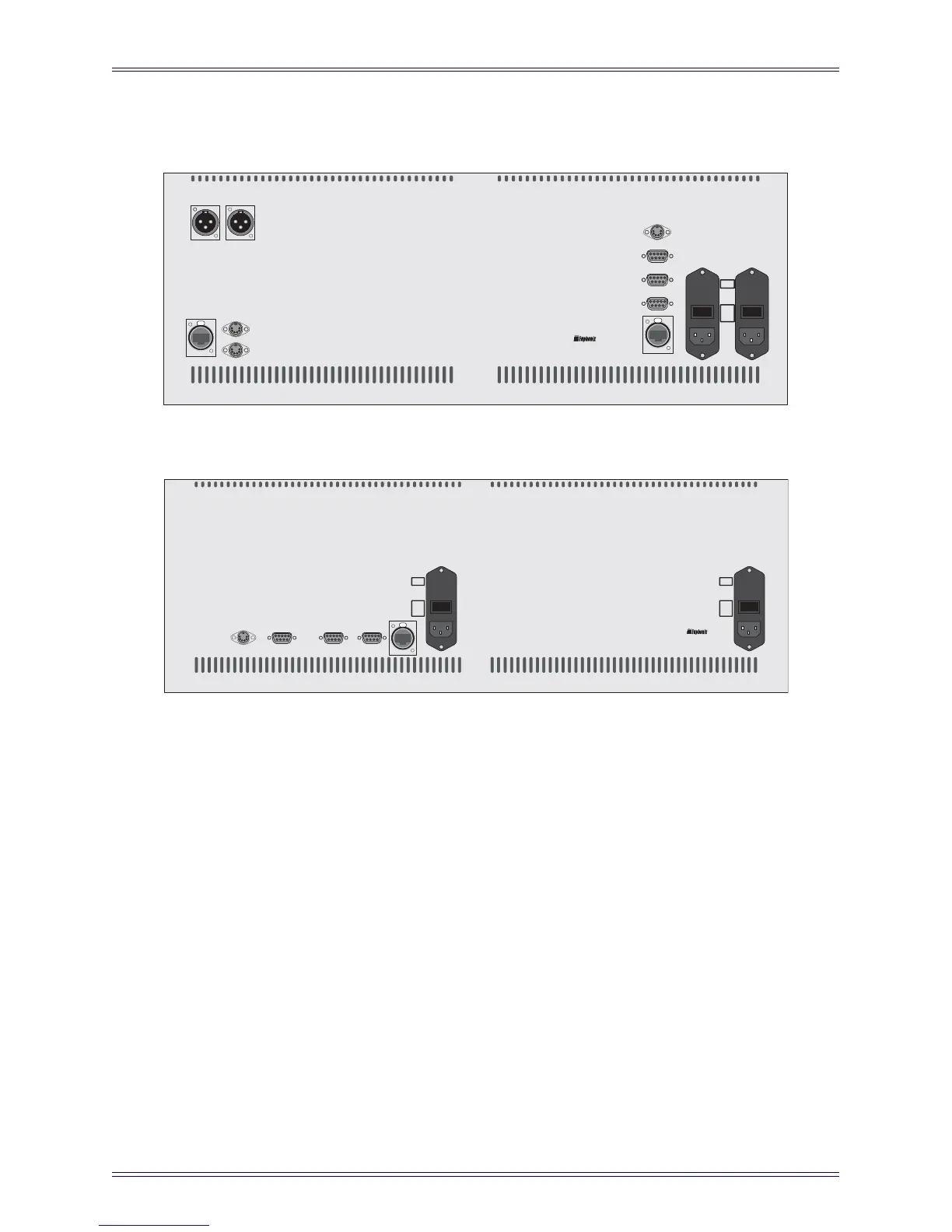
Figure 3-3 CM404 Rear Panel
Figure 3-4 CM416 Rear Panel
The Max Air Console consists of several modular components: the CM416 with 16 physi-
cal faders and controls, and the CM404 center section. Each component has the following
connections:
Power Connectors (IEC): Accepts two standard IEC power cords (provided). Two au-
toranging switching supplies accept voltages between 100–240 VAC, 50–60 Hz.
LAN Port (RJ45): Connect to EuCon Network Switch via RJ45 through the console
Ethernet harness (provided).
To KVM Extender (RJ45): Connect to KVM extender (CM404 only).
Talkback (XLR): Connect to the internal and external talkback microphones.
Keyboard and Mouse (PS2): Connect to the keyboard and mouse or trackball.
Serial 1, 2 (DB9): RS232 serial ports (for service only).
Service (DB15HD, PS2): VGA video and keyboard connection (for service only).
SERIAL 1SERIAL 1
AC IN 1AC IN 1 AC IN 2AC IN 2
SERIAL 2SERIAL 2
LANLAN
MOUSEMOUSE
TO KVM
EXTENDER
TO KVM
EXTENDER
KEYBOARDKEYBOARD
INTERNAL
TALKBACK MIC
INTERNAL
TALKBACK MIC
EXTERNAL
TALKBACK MIC
EXTERNAL
TALKBACK MIC
Caution:
To prevent risk
of fire, replace
fuse with the
same type and
rating.
T 5.0 AH
250 V
CM404CM404
~100-240V
AC
50-60 Hz
250 Watts
I
O
I
O
SERVICESERVICE
I
O
I
O
Caution:
To prevent risk
of fire, replace
fuse with the
same type and
rating.
T 5.0 AH
250 V
Caution:
To prevent risk
of fire, replace
fuse with the
same type and
rating.
~100-240V
AC
50-60 Hz
250 Watts
T 5.0 AH
250 V
LANLAN
AC IN 1AC IN 1 AC IN 2AC IN 2
~100-240V
AC
50-60 Hz
250 Watts
CM416CM416
SERIAL 1SERIAL 1SERVICESERVICE SERIAL 2SERIAL 2

 Loading...


