Euphonix Max Air Installation Guide Interconnecting System Components
20
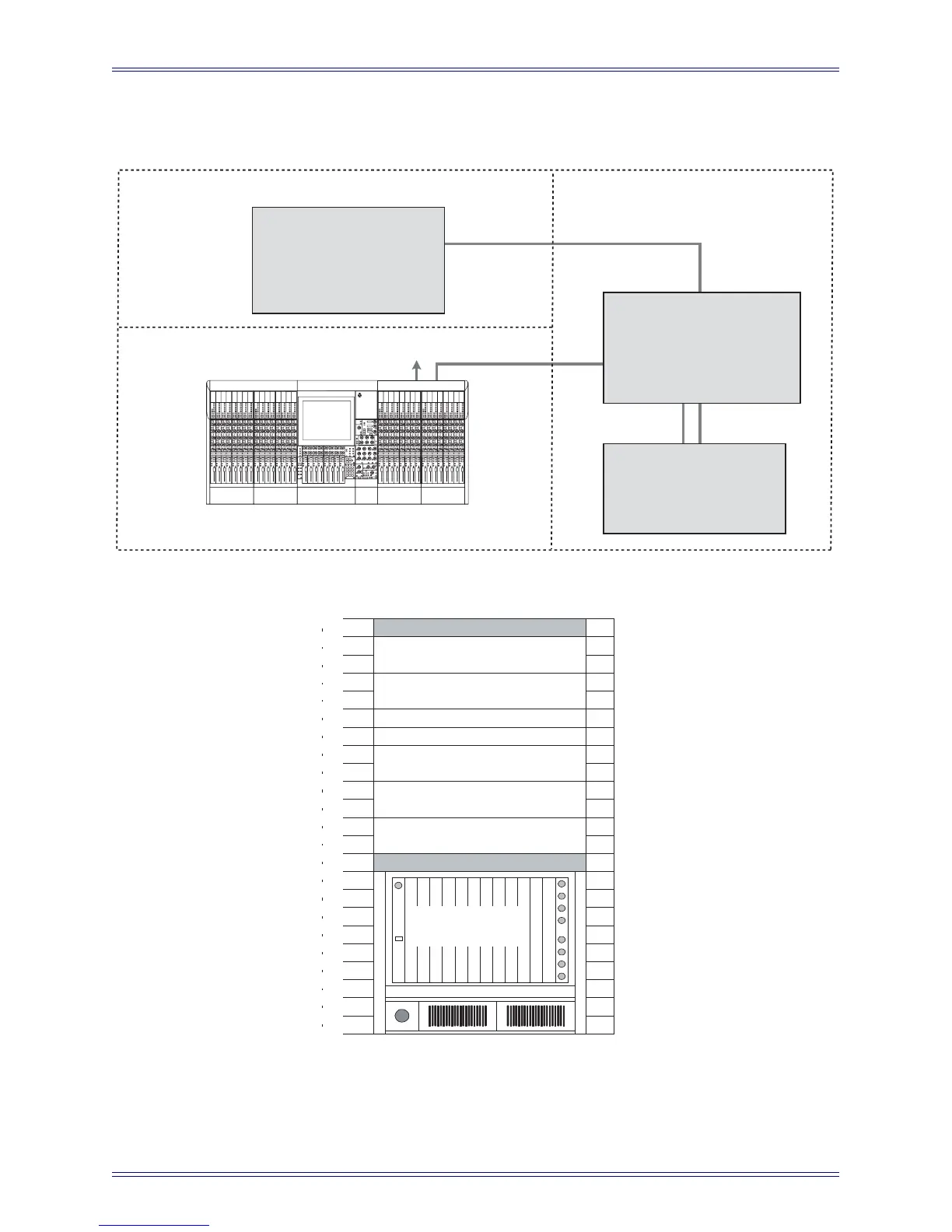
Typical Max Air Room and Equipment Layout
Figure 2-1 Typical Max Air Room and Equipment Layout
0
1
2
3
4
5
6
7
8
9
10
11
12
13
14
15
16
17
18
19
20
21
22
23
Leave Open
PC253d (Frame #1 Pilot)
PC253i (Interface Pilot)
GP132
SC261 (System PC)
EH 224 (EuCon Switch)
MIDI Interface
Leave Open
Frame #1
SH612 (Studio Hub - Optional)
Studio
Optional
Studio I/O
Digital Frame
IF Control
MADI
Sync
Console Umbilical (Eucon)
Talk Mic (to Mon IF)
Control Surface
Machine Room
Control Room
Machine
Room I/O
ML 530 Mic-Line IF
AM713 A/D Converter
Analog IF & Patch
Digital IF & Patch
Cue Feeds (from Mon IF)
Listen Mics (to Mon IF)
AM713 A/D Converter
DM714 AES/EBU-to-MADI IF
MC524 Monitor IF & Patch
MA703 Monitor D/A Converter
EuCon Switch
SC261 System Computer
MIDI Express XT IF & GP132
PC253i Interface Pilot
SH612 Studio Hub (Optional)
PC253d Digital Pilot
DF64 Digital Frame

 Loading...


