43
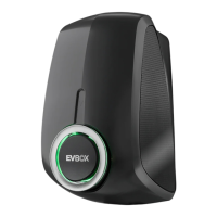
2. Optionally, install and connect the CT
coil cable
a. Strip the outer insulation of the cable
to a length of 50 mm, then strip the
individual wires to 7 mm.
b. Connect the signal wires.
Insert the CT coil cable into the PCB connec-
tors (MCVR 1.5/ 3-ST-3.81) and secure the
wires using a screwdriver.
c. Connect the PCB connectors to the
power board.
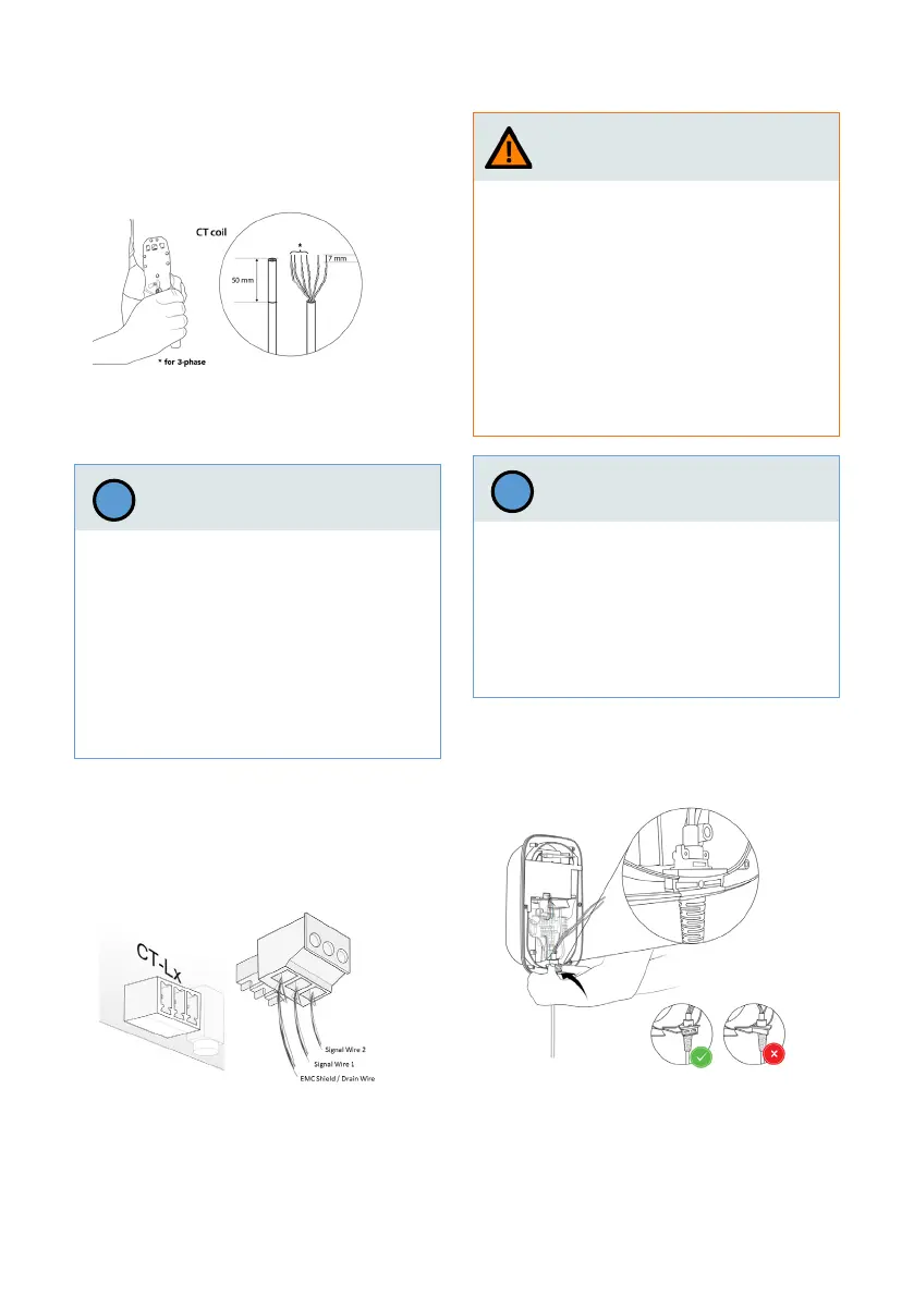
43
a. Place the charging cable holder on the
main assembly with the V-shaped side
towards the main assembly.
3. Install and connect charging cable.
Connecting the signal wires of the CT-coils
incorrectly may result in improper instal-
lation, which could cause the wallbox to
exceed the congured maximum charging
current.
› Make sure that the signal wires of the
CT-coils are connected to the middle and
right pins on the power board connector.
The left pin is reserved only for shield
connection of such wires.
Notice
!
Warning
An incorrect routing of the wires of the
charging cables will result in improper ins-
tallation, which could cause a malfunction
of the ground (earth) leakage detection
safety feature of the wallbox.
› Do not route the PE and CP wires of the
charging cable through the ELS sensor.
› Route only the blue (N), brown (L1)
(as well as black (L2) and grey (L3) for
3-phase version) wires through the ELS
sensor.
An incorrect mounting of the charging
cable holder in the main assembly may re-
sult in improper installation, which could
cause damage to wallbox components.
› Make sure that the charging cable is posi-
tioned with the V-shaped side towards
the main assembly.
Notice
!