44
English
Color coding for the provided EV charging cable
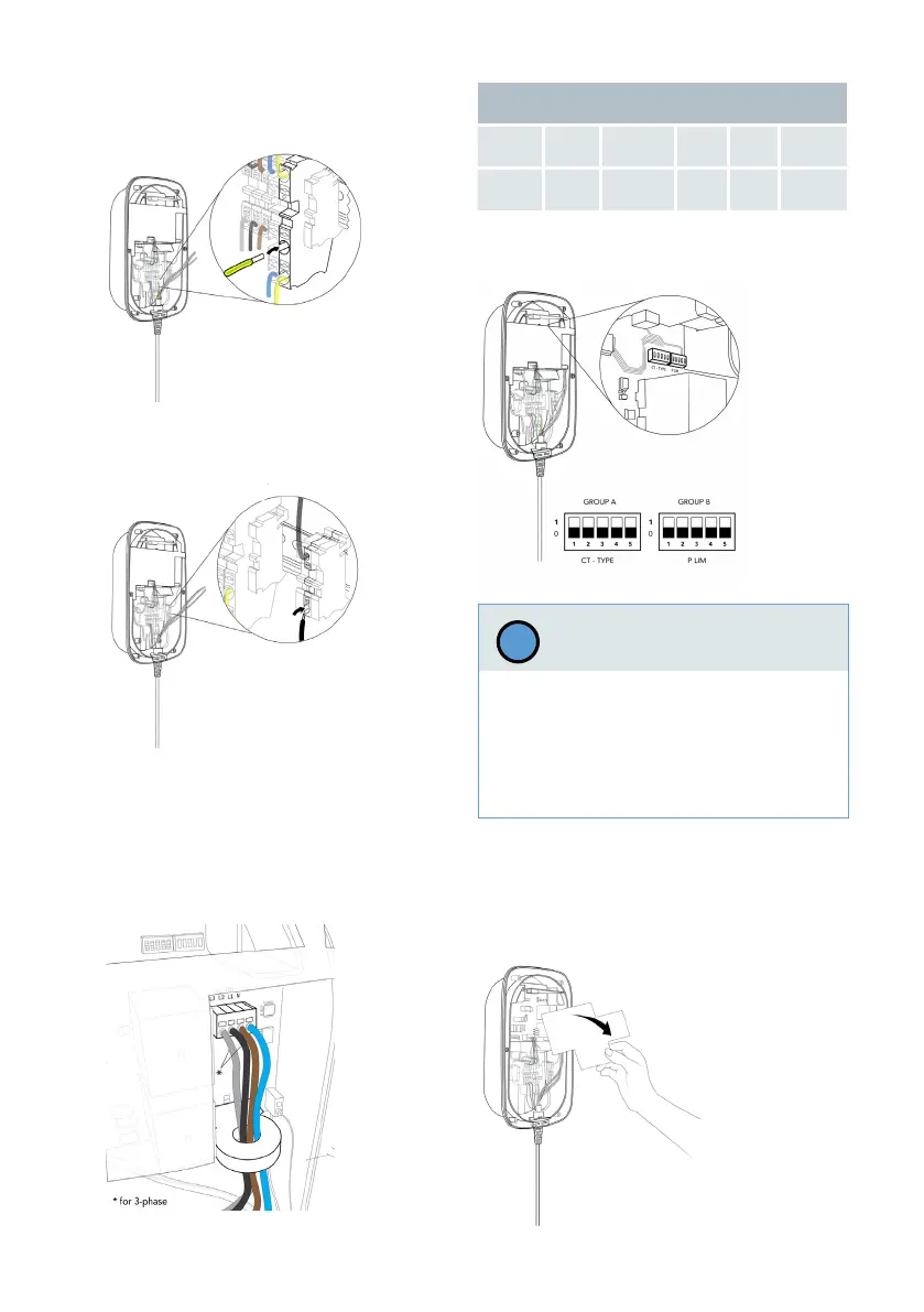
Wires L1 L2 L3 N PE
Color Brown Black Grey Blue
Green /
Yellow
b. Connect the PE wire of the charging
cable to the second available slot of the
PE feed-through terminal.
c. Connect the CP wire of the charging
cable to the CP feed-through terminal,
located at the end of the DIN-rail.
d. Route Neutral (N), L1 (as well as L2 and
L3 - for 3-phase version) wire(s) of the
charging cable through the ELS sensor.
Connect them directly to the terminals
on the power board according to the
table below.
4. Set the DIP-switches.
See chapter Set DIP-switches for the DIP-
switch settings required. (before mounting
the frontcover)
5. Remove cardboard cover.
A damaged communication board may re-
sult in improper installation, which could
cause unstable wallbox functionality.
› Be careful not to damage the commu-
nication board during DIP-switches
conguration.
Notice
!