Alarm I/O pin assignment
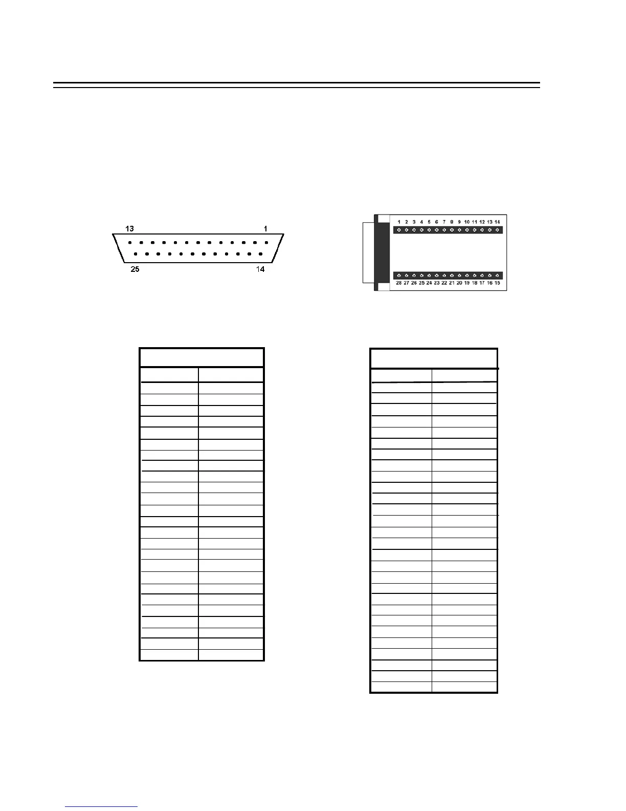
The alarm connector, Figure 1, is used to provide one sensor alarm input for each camera input.
For easy operation, an alarm extension board, Figure 2, is provided to connect to the alarm connector.
Each alarm input requires two wires, one wire connects to the desired alarm input pin, the second wire
connects to the ground.The alarm signal assignment is shown at the following.
<Figure 1>
D-SUB 25 pin female connector (DVR)
<Figure 2>
PR16D00400 Alarm extension board (HOST)
PIN # NAME
1GND
2ALM 1
3ALM 2
4ALM 3
5ALM 4
6ALM 5
7ALM 6
8ALM 7
9ALM 8
10 --------
11 --------
12 --------
13 --------
14 --------
15 --------
16 --------
17 --------
18 ALMRSTO
19 REC
20 --------
21 DISKFULL
22 --------
23 ALM-N.C
24 ALM-N.O
25 ALM-COM
DVR
HOST
PIN # NAME
1GND
2ALM 1
3ALM 2
4ALM 3
5ALM 4
6ALM 5
7ALM 6
8GND
9ALM 7
10 ALM 8
11 --------
12 --------
13 --------
14 --------
15 --------
16 --------
17 --------
18 --------
19 ALMRST
20 REC-IN
21 GND
22 --------
23 DISKFULL
24 --------
25 ALM-N.C
26 ALM-N.O
27 ALM-COM
28 GND
APPENDIX C : Alarm I/O Assignment
APPENDIX
77