76
Electrical System
Additional 12 Volt Switches
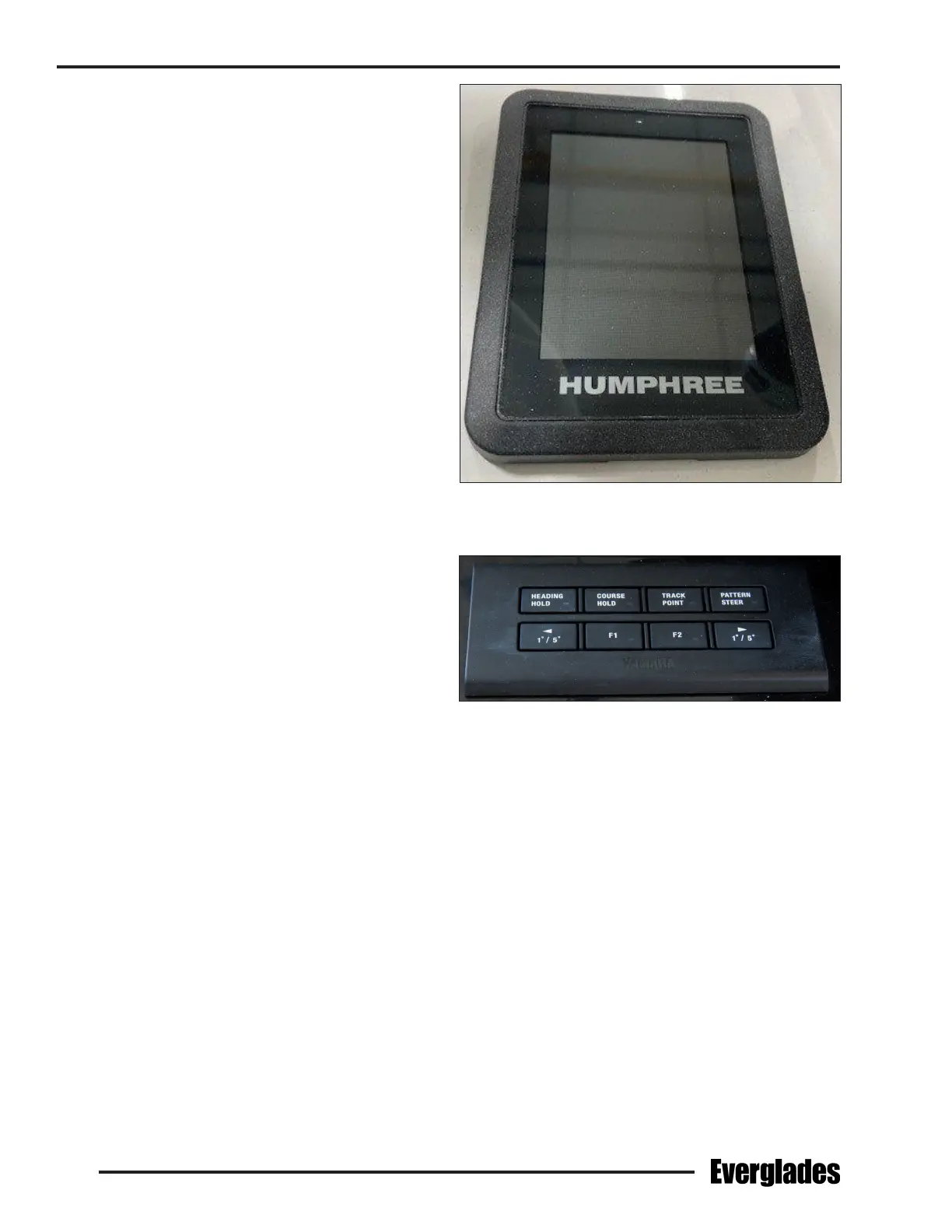
Trim Tab Control Panel (Standard)
Located in the helm or hardtop electronic panel.
This panel controls and monitors the trim inter-
cepters located on the transom of the boat. It is
protected by a fuse located in the accessory fuse
panel on the fuse and breaker panel in the battery
compartment. Refer to the Helm Control Systems
chapter for detailed information on the operation
of the trim tab controls.
Engine Trim and Tilt Switches
Located in the helm. These switches are typi-
cally installed in the engine throttle and shift
controls. They control the trimming and tilting
of the engines. Refer to the Helm Control Sys-
tems chapter and the engine owner’s manual for
information regarding the proper use of the tilt
and trim switches.
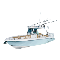
Auto Pilot Switch Panel (Optional)
Located in the helm. Controls the auto pilot. It is
protected by a fuse located in the accessory fuse
panel behind the helm or other circuit protection
provided by the auto pilot manufacturer. Refer
to the auto pilot owner’s manual for details on
operating the control pad.
Lighting Color and Brightness Controls
Spectrum color is controlled with the use of Lu-
mitec’s proprietary TTP (Timed Protocol Technol-
ogy). TTP is the use of brief o/on toggles of the
light’s power switch to dim the light, select color
output or cycle through the light modes.
Underwater Lights:
The light will start in white and then cycle through
the complete color spectrum, fading from one
color into another, over a period of 15 seconds.
After the initial 15 second cycle, the light will
continuously cycle through all the colors every 3
minutes. Once the light is turned on, or at any
point in the color cycle mode, it can be locked on
a color by a brief o/on toggle of the switch at
the desired color. To reset the light, turn the light
o for 3 seconds and the light will reset to the
beginning of the cycle. Once a color is locked in,
you may also toggle the power switch to restart
the color cycle.
Down Lights and Utility Lights:
The light will turn on in white and ramp up to full
intensity over a 4 second period. The light will
remain on white until the color cycle mode is se-
lected. You may dim the white color by toggling
Trim Tab Control Panel
Typical Auto Pilot Switch Panel
the switch as the light ramps up. Interrupting
the ramp up period sets the light at a lower level.
Once the white light is on, toggle once to enter
the color cycle mode. A 15 second color cycle is
followed by a continuous 3 minute color cycle for
more precise control. The color cycle will always
start with red for easy access to the night vision
mode. To select a color as it appears, toggle the
switch once and the light will lock to the selected
color. To dim the color, select the desired color with
a toggle of the switch. Then immediately toggle
again to set the color intensity. Interrupting the
ramp up period sets the light at a lower level. To
reset the light, turn the light o for 3 seconds and
it will reset in the white mode.