CP-2272E
Page 2 Revision 1.0
2. INSTALLATION
2.1. REAR PANEL
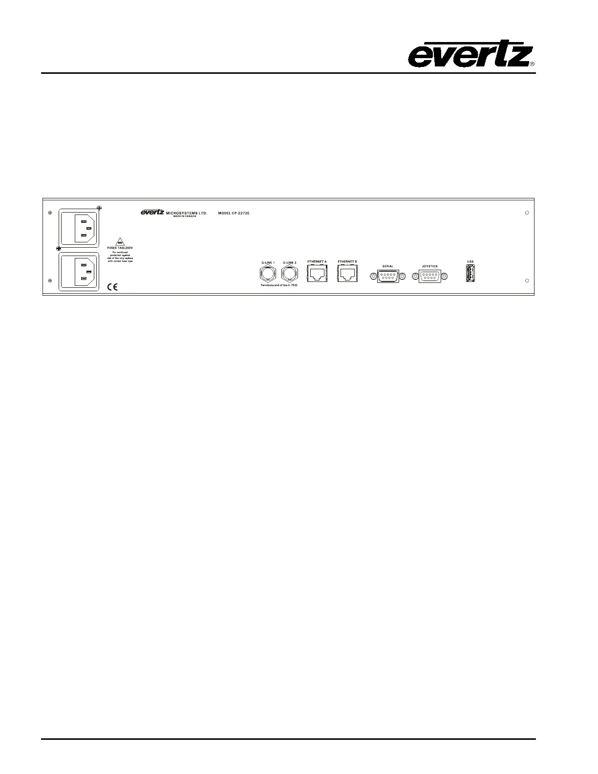
Figure 2-1 shows the rear view of the CP-2272E control panel. The CP-2272E is a 2RU panel with
various connection ports. Sections 2.1.1 to 2.1.5 describe the function of the connectors on the rear
panel.
Figure 2-1: CP-2272E Rear Panel
2.1.1. Serial Connections
SERIAL: Serial port 1, female 9 pin D connector that is used as the RS-232 console port.
2.1.2. Joystick
This male DB9 connector is used for connection to a camera control unit to allow the joystick push
buttons to override the router.
2.1.3. QLINK 1 / 2
These ports are not used at this time
2.1.4. USB Control
This USB 2.0 Port is used for USB-based firmware upgrades of the CP-2272E.