184
OILING SYSTEM
OILING SYSTEM TESTS
Oil Injection Pump Circuit
Resistance Test
IMPORTANT: The complete oil injection pump
electrical circuit includes EMM alternator output,
the engine wire harness, the injection pump wind-
ing and connectors, and the oil injector control cir-
cuit of the EMM. Check continuity of all wiring and
connections.
Disconnect the battery cables at the battery.
Use an appropriate test probe to make a connec-
tion to pin 1 of the oil injection pump connector.
Calibrate a digital multimeter to the LOW OHMS
scale and measure the resistance between pin 23
of the EMM J1-B connector and pin 1 of the oil
injection pump connector.
Results:
• An infinite reading (∞) indicates an open circuit.
Isolate the faulty wiring, connection, or injection
pump winding. Repair faulty wiring or replace
faulty component and retest.
• For a higher than expected reading, test resis-
tance of the injection pump. If injection pump
resistance reading is approximately 22 Ω, injec-
tion pump winding is good. Isolate faulty com-
ponent. Repair faulty wiring or replace faulty
component and retest.
Oil Injection Pump Function Test
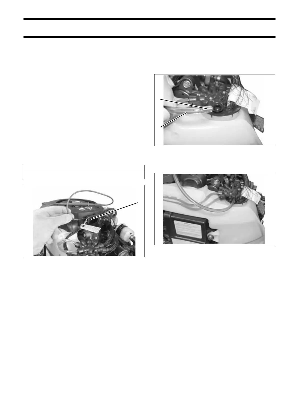
Remove oil distribution hose from fitting at oil dis-
tribution manifold. Do not lose the brass hose sup-
port.
Temporarily install a length of oil hose.
Start the outboard and observe oil flow:
• Oil flows from hose, compare to oil flow at other
distribution fittings
• If one or more fittings fail to flow oil, replace the
oil injection pump assembly.
Reinstall hose into manifold.
IMPORTANT: Make sure hose support is in
hose and hose is fully inserted into manifold.
Refer to Oil Distribution Hoses on p. 186.
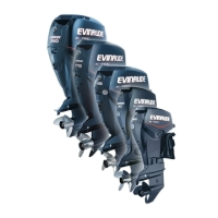
Oil Injection Pump Resistance
22 Ω
1. Oil injection pump connector (pin 1) 006572
1
1. Oil distribution hose
2. Hose support
002362
002377
2
1
 Loading...