61
INSTALLATION AND PREDELIVERY
FINAL ADJUSTMENTS
2
Trim Sending Unit Adjustment
Tilt the outboard and engage the tilt support.
Temporarily install a thrust rod, P/N 436541, in the
number 3 hole.
Loosen the sending unit screws, to allow the
sending unit to pivot.
Disengage the tilt support. Lower the outboard
against the thrust rod.
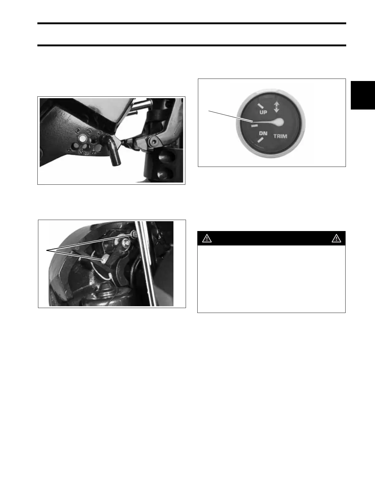
Observe the trim gauge. If the needle does not
show center position, tilt the outboard up and
adjust the sending unit by pivoting it up or down.
Lower the outboard against the thrust rod to check
adjustment. Repeat adjustment, if necessary.
After adjustment is correct, tilt the outboard up,
tighten the two sending unit screws, and remove
the thrust rod.
29072
1. Screws 27339
1
1. Needle at center position 000662
WARNING
When the outboard is returned to the cus-
tomer, the trim limiter rod must be
installed and in the same location as it
was when the motor was brought in for
service. Leaving the trim limiter rod out, or
changing the adjustment, could allow the
motor to unexpectedly trim in too far and
cause loss of control.
1
 Loading...